Mopar1973Man
Owner
-
Joined
-
Last visited
Everything posted by Mopar1973Man
-
Have you updated the flash possibly? You are running the correct vehicle type I just wonder if the firmware needs updating.
-
Funny the OEM tierods on my truck lasted 350k miles. Must not be too bad of a design. But I've got the reason why I kept failures down. I've never ran larger tires. I'm actually running smaller than stock size. 265's what the truck was built with. I went to 235's shortly after the 3rd year. Then recently dropped to 245's which is a 1" shorter. Now I've reduced the stress on everything and not required to upgrade at all. Even reduced the stress on driveline and transmission too. Kind of like 190k miles on my current brake pads and won't need to replace them for another 150k miles roughly. I'm in the game for longevity.
-
The last thing I've seen where transmission pressure was low, the filter was filled with debris.
-
I was right... Too retarded. 1500 RPM = 15° 2000 RPM = 18° 2500 RPM = 21° 3000 RPM = 24° MAX = 27° Low psi reduct 4° Timing reduct scaling 50% Light throttle load limit 30% Adjust to what I posted...
-
Too retarded if it got grey smoke. What is your current timing settings?
-
Remember TV cable adjustments will change shift points and pressure. If the TV cable is not adjusted properly then the shift pattern can be altered.
-
Nice to be back home. Wow! what an adventure. I can say living in the rim area of big cities you might not have to travel far or get fuel often being the distance is shorter but MPG sure sucks. For that week of being in Parma, ID and running back and forth to Ontario I barely made 16.61 MPG. Ugh! I'm getting back on track and be rolling from home from here on out. As for the flooded area, it's like a bad dream it all vanished like it never happened. The mudslides you can see the mud and debris around the edge of the road. Then the belly washes are still present for the smaller one. The river flows are down for both Weiser River and Little Salmon River. Like this morning it's raining again. I'm going to keep an eye on the weather forecast and what I see in the rivers again. It is so nice to be back home.
-
I ran the first 10 years with a DiPricol fuel pressure gauge direct plumbed for 10 years. Just a needle valve (NAPA WH6820). Now in my second 10 years of ISSPro EV2 fuel pressure gauge with air brake line from the tap point to the sensor on the fender. Using ISSPro snubber. Looks similar to this.
-
What are you asking me to tear out my vacuum system and replace it with all air brake line and upgrade?
-
Also used for longevity. Like in my case I don't want to do head gaskets every 300k miles. The tinsel strength of the ARP 425 should keep the head from curling on the end over time. Where normal head bolt will give up and start to stretch allowing the head to curl. Stock head bolts are known for the curl problem. Then like @Bullet mentions that the clamping force to allow for more boost pressure is bonus. I done the math long ago but 30 PSI of boost and just the crank spinning without fuel being injected you reaching 1,100 PSI in the cylinder. Yes you need to keep the clamping force on for the head when you adding lots of timing and fuel. I was doing 47 PSI of boost on the stock gasket. I was lucky and not blown the compression part but the head curled and started leaking coolant out the rear passenger side of the head. My case is more about heat cycles and bolts getting weak. Cost me $2,000 with the valve guides, seals, machine work, gasket kit, and the ARP 425 stud.
-
Now I've got to wait till Tuesday to get back to the RV to install them.
-
Ditch the isolator. Install a WH6820 needle valve from NAPA. Warning the price jumped up on them. I would look towards a snubber from ISSPro which is a sintered metal snubber.
-
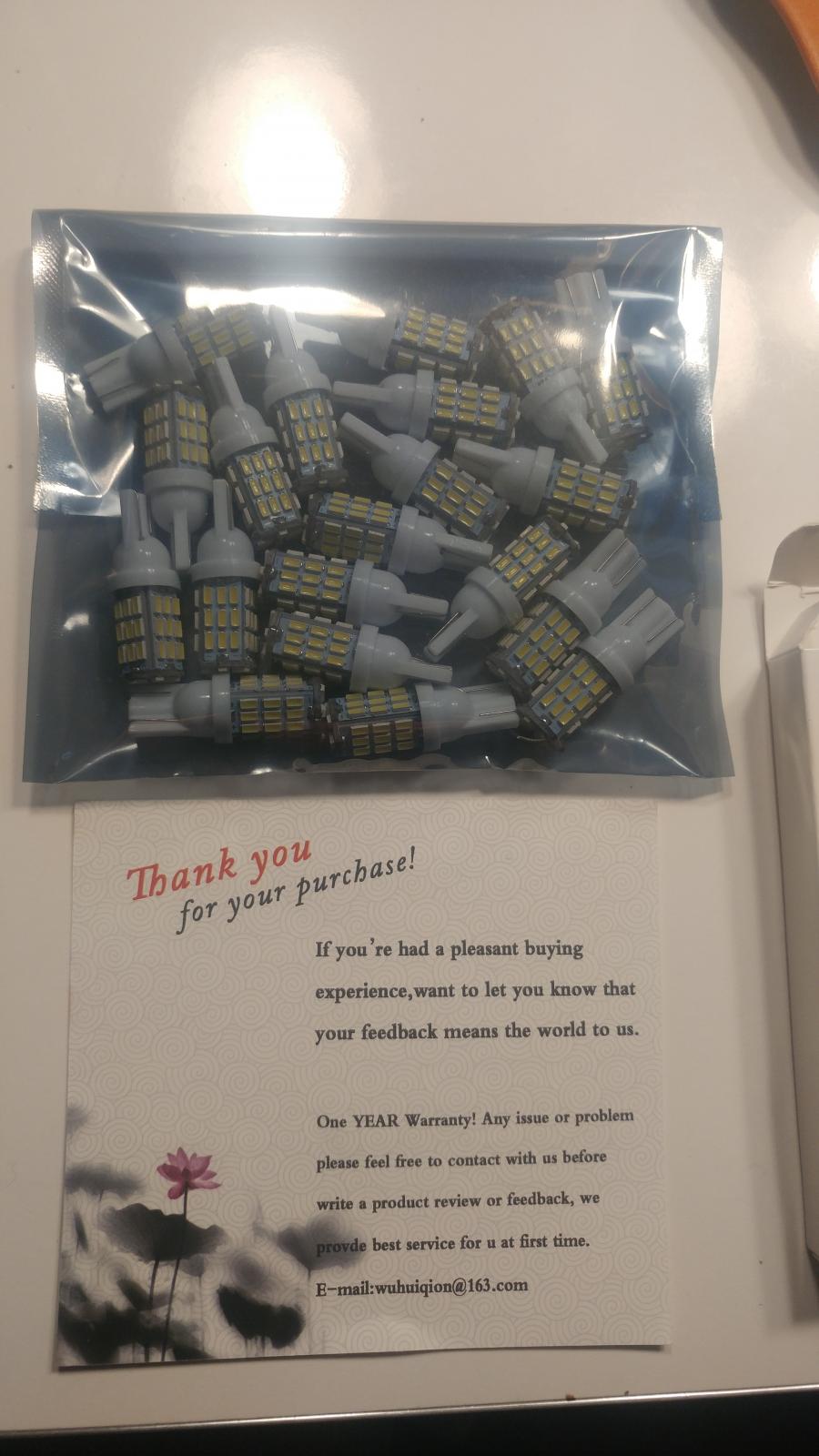
Finally got the LEDs for the RV. It will be nice to upgrade the RV. Like last night I was laying in bed but the overhead light was getting hot and smelling of burnt plastic again. Be awesome to have cool running lights like whats in my truck interior.
-
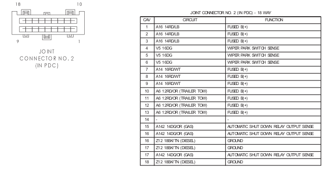
Since I made it home... Here is the joint connector 2 pin out... Looking at the joint connector I'm going to bet money either the wrong fuse is being used or excessive electrical load is placed on the joint connector. Being a majority of it is +12V power supply and only 3 pins are grounds. Then being trailer power is from here then it could be a trailer electrical issue and/or wrong fuse size used. Yes, I've seen dealers increase the fuse size and cross out the old fuse size.
-
In my case did exactly that and 2k miles later the transmission failed. While you there take note of the debris in the pan it might be time for rebuild.
-
Just realized the Member map function was missing on the site. I'm attempting to rebulid it and get it back up and running.
-
Because this body was more designed for the V8 gas engine than the I6 Cummins diesel. This is why the vacuum pump was added and the vacuum comes out of the dash on the passenger side. As you see the 3rd gen up stopped with vacuum and went to electric stepper motors.
-
I was being honest. I don't use any thread locker or anything on frame stuff... I'm in the rust world too and I typically put anti-seize on everything. Other than that you'll be cutting it off with a torch in the future. Again being serious... My last thing to do on the axles was doing wheel u-joints and 4 hours beating on a unit bearing to remove it.
-
Two grounds to check. Lighting ground is on the front driver side fender near the headlight. Then the panel ground is in the driver side kick panel in the cab. You might also check your fuses (corroded fuses) which produce weak power for the circuit.
-
With all that rust I would assume it would self lock in a few weeks.
-
I'll most likely go to WalMart and get some Sony Explodes...
-
Man every time I see people attempting to retrofit T style in glad I've kept my Y steering which has worked perfect for years and nearly 400k miles.
-
When it comes time ill rebuild my vacuum system completely with air brake tubing. Never worry again. Even on my 1996 gasser I will build it as well with air brake line. A lot of the mistake is making sure to route away from heat and friction.
-
I had to grab mine with channel locks to pull the wiper arms off. Once removed I greased the inside of the spline part. Road salts corroded mine some.
-
I dug deep in my pockets and got the ARP 425 studs. I seems to always be on the border line of everything. At least I don't have to worry about head gasket.