


Mopar1973Man
Owner
-
Joined
-
Last visited
Everything posted by Mopar1973Man
-
I live this kind of life now up here in my area. Yeah, I might have internet but no cellphone. Power, I'm all set for power outage being I've got solar, hydro, and battery power. Water and sewer for me are all self-contained here. Water is pumped out of my well and sewage is handled in my septic tanks and drain field. I'm way ahead of most people. I'm already used to the idea of being in the forest alone and traveling the back roads of Idaho to get places.
-
Even my four 100w bulbs didn't have enough heat at near zero temperature to keep the snow and ice from freezing to the lenses this last winter.
-
Just be aware if you drill a hole in the cap it just means a better chance of getting water in your fuel. The tank is a spring loads check ball so it typically held shut so chances of water entering is rare. So using soft wire and compressed air you should be able to free the dirt and blow it out.
-
I'll most likely stick with white lights. I know these will fit where the normal factory fog light typically is installed. I've been out measuring and seeing what I can make fit. Time to say good bye to... They worked good for all these years but time to upgrade to way better lighting. I have to say thank you to few people once again @Me78569 and @jlbayes for jumping into the HID lighting game to make me reconsider lighting. Now that I'm digging I'm finding better options and better quality lighting than most people are buying. Yeah I'll admit HID's are expensive to have them ready made for your truck but even the LED driving lights are expensive too but high-quality optics, polycarbonate lens, and reduced electrical load on the alternator it a win-win. I'm not seeing any end in sight for my travels. Till we find a dialysis nurse for Mom I'll continue to make my 250-mile trips to Ontario to keep her alive...
-
Actually, they are the new beginning... At least these folks know how to operate without all the modern technology or when all the modern technology fails. I tend to float back and forth on the fence on both sides. I know about the old school methods and modern stuff as well. I can see so many people total lost because they are dependent on the system and what Gov't agencies provide them. As you pointed out "when the end comes..." there is always a new beginning. Look back at history fall of one empire to start another. There were always people that had to restart again with the basic knowledge.
-
Impressive...
-
You'll notice a few things... EGT's will be lower, Coolant temperature will be higher about 5*F than typical. Boost will be lower and engine load will be lower as well. I did something crazy and towed my RV back from Parma, ID without dropping my tune or changing. I left it at my current settings. Really wild to see the changes. I towed home at 55 MPH in 4th gear on grade and 5th on the flats. EGT's were considerably cooler climbing grade with cruise set I'd never even reach 1,100*F at 20-25 PSI of boost but held my set speed no problem. Engine coolant was notably higher Flat running was 198-202*F and climbing grades it topped out at 210*F still within the normal realm but EGT's never got even close to 1,200*F ever. Pulling power was super strong and exhaust was still fairly smoke free. Here is my current tune... Still pretty steep timing but still doing rather well will MPG's. iQuad-Economy-2017-10-13-02.37.072107239207.json
-
I look at it this way to rely on any media or gov't information. Get your own sources of information. You'll find out that alphabet media and alphabet gov't is worthless and you can stand on your own feet. I know there is other factors out there like weather modification etc. But look at what our forefathers have done traveling across the USA and managing to live without assistance or information form these groups. Still this day there are people in the country out here without power the only bill they pay is the phone. Yes I'm talking about some serious back country folks that don't need TV and new media. They do it themselves.
-
I could do that fix by removing the drive shaft and sitting under the truck. Little piece of wire and a bit of compressed air to clean out the vent.
-
Made the phone call to PIAA and talked to a tech there about lighting. Very helpful and noted that for my back contry road conditions with rain and snow he suggested yellow ion driving lights. So looking at the inventory I've come up with either... Yellow ion lights... http://www.piaa.com/store/p/845-LP270-Ion-Yellow-2-75-LED-Driving-Light-Kit-SAE-Compliant.aspx or... Staying with white light... http://www.piaa.com/RF3LED http://www.piaa.com/store/p/648-LP270-2-75-LED-Driving-Light-Kit-SAE-Compliant.aspx Has anyone used yellow lights before and how did they work for you?
-
Tank vent is plugged...
-
Absolutely true. So now with that knowledge I'm going to upgrade my fog/driving lights to something that floods area ahead of me.
-
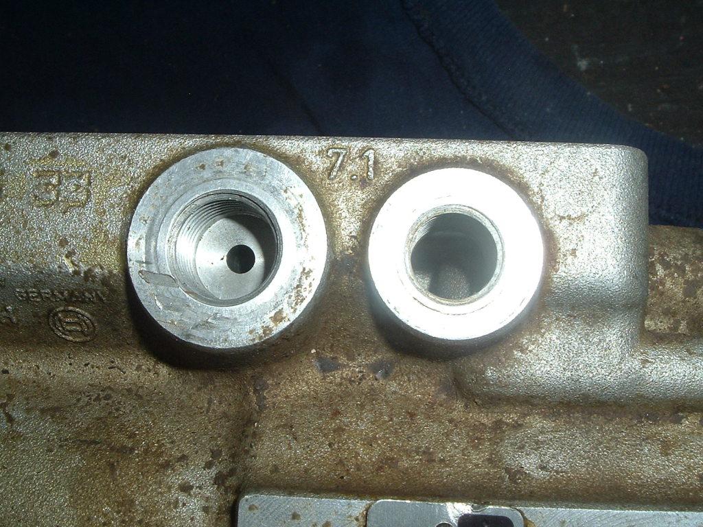
Won't do you any good to change the return fuel line sizes. If the port coming out of the VP44 is already small there is nothing to be gained. Return port is on the left and supply is on the right.
-
Holy Crap dude don't turn on your high beams. You'll be able to see every damn snowflake falling to the ground. You'll never see the highway any longer because of being blinded by brightly lit up snowflakes.
-
I really could have used those PIAA lights tonight. Came home in a snowstorm and had to keep my low beam on. So between looking at the snow coming at you and limited field of light still my Morimotos were brighter than my old 100w aircraft light but still not a good field of light. I'm going to be making some phone calls in the morning to PIAA.
-
I just came home in a snow storm... Oh how fun...
-
Might check out @Me78569 thread on using 330 bar injectors. Also stock pop pressure is 310 bar.
-
Might just fine that you'll gain some more power and MPGs to boot.
-
Exactly. Android software typically is very low price or FREE. Where most all iPhone or iDevice stuff is expensive. Like I've got all Linux PC's and pay nothing for software and all Android phones and again low to FREE software. Even picked up a cheap tablet for $40 buck and use it for the OBDLink for a long time. Current setup... Old Setup...
-
Not that great... 2 Cycle Oil scored better. Also the added cetane reduces your BTU content of the fuel. Right out of the ASTM labs documents...
-
That's fine... The only difference is the weather rock is happening right now. So if something serious is coming you'll never have any warning to get out, leave, or prepare for bad weather. I'm tired of the surprise storms and not having good warnings. My old weather station only did temp and humidity and a gamble at future weather which that is 15-year-old technology so it was hit and miss. Now with the ability to see a true barometer number, I can see the weather coming and how severe it could be. So I can look back hours ago and see if the weather is change and how. Where the previous didn't log anything. Again back to the madness, I tend to enjoy the fact I'm long ways from the Madness of the Big Cities. It's up to me to protect my family and myself. I'm not going to rely on Gov't agencies to forewarn me or give assistance. I'm a red-blooded American that will stand on his two feet, not like the Millenial or Snowflake generation always with their hand out looking for help. God helps those who help themselves.
-
Another Cummins 4BT living once again in a new body...
-
I tend to favor the OBDLink series dongles being there is constant firmware updates. I also prefer the bluetooth series over the WiFi but all iPhone (or Apple) users have to use WiFi option.
-
Valve lash incorrect. Leaking head gasket (Between cylinders or outwards). Leaking injector copper washer. Improper injector installation. Cracked head. Cracked piston(s). Piston rings washed out from leaking injectors. Injectors are on there last leg... I'm finding out that every 100k miles are good time to just consider replacing injectors. You can go past that but injector quality degrades and pop pressure starts to fall so the atomization starts to fail.
-
No problem here... Inverter will kick in by itself and I won't notice power outage. Just keep you away from the bolt pile and the intercooler tubing...


