Everything posted by Mopar1973Man
-
I had a customer that wanted me to change his clutch but when I pulled the transfer case the gap between was fully of ATF and trans gear lube. Previous installer silicone the mating faces and plugged the drain hole. I changed both transfer case and transmission seal to have it leak again. Transmission had a bad bearing.
-
Shaft bearing is bad most likely.
-
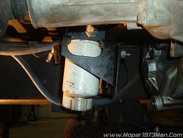
Like my truck the AirDog is right behind the transfer case. Guarded by the transfer case and skid plate.

-
Shouldn't matter being a long as the fuel lines are parallel to the frame and the inlet is facing rearward.
-
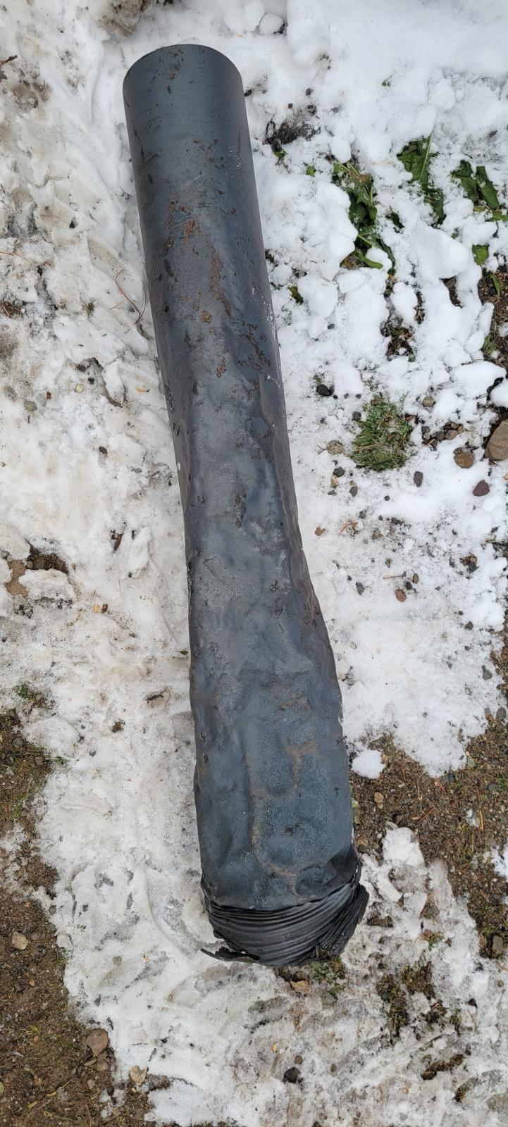
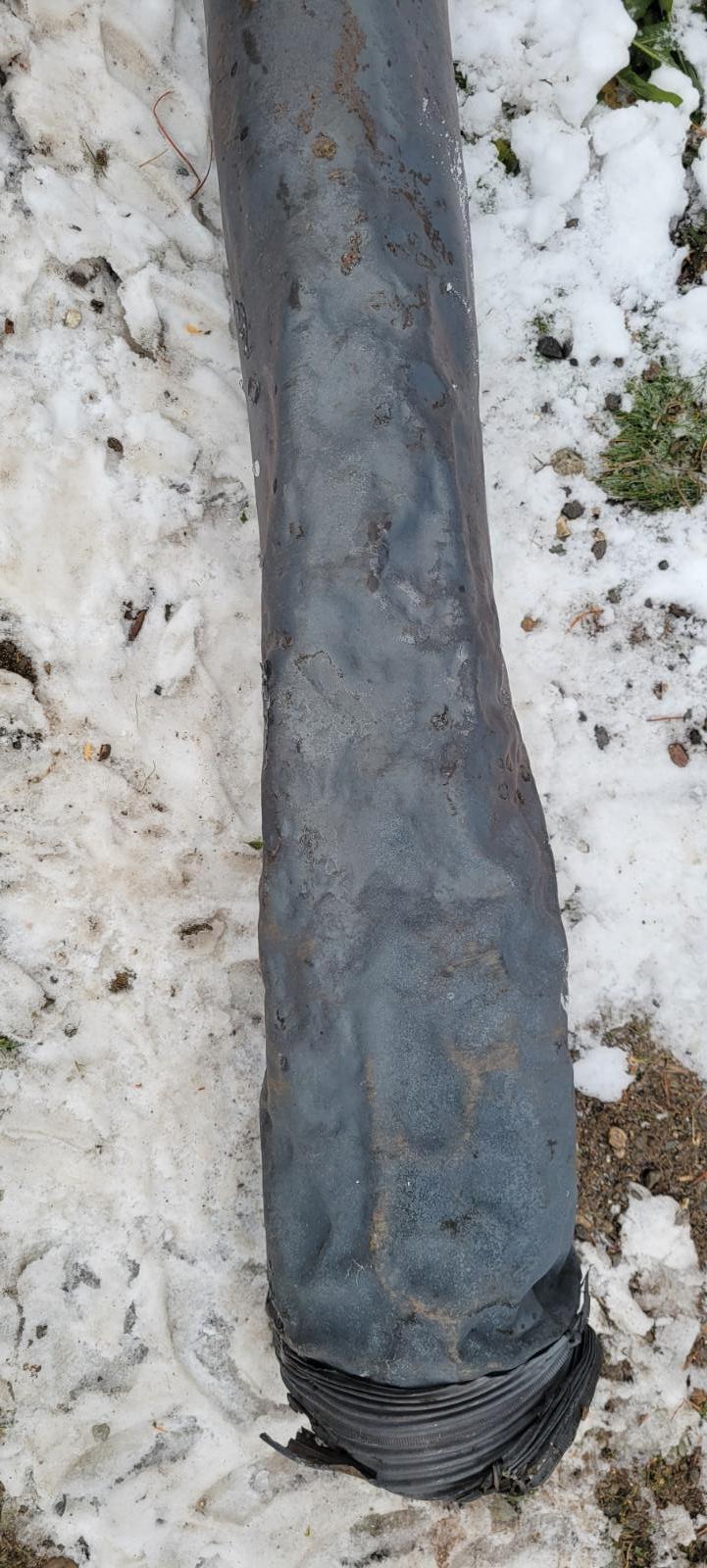
Found the old pipe this was my stainless pipe and how it failed. Like I said stainless will melt and fail so be very careful. From what I remember it was 904 stainless stove pipe seamless as you can see the pipe got hot and start to distort.
-
Here would be my suggestion. https://www.amazon.com/dp/B086BQJD85/?coliid=I2VRUFEAK8A93W&colid Magnetic Induction Heater which will heat that block heater up and should allow you to get the heater unscrewed. Typically I just get a big socket and long handle breaker bar and they typically come out. Ford 7.3L are no different and just down by the oil filter on the driver side. I've change 2 of those without even drain coolant.
-
Be aware stainless does NOT hold up to the same amount of heat that steel can. I found out for my last person that was renting my guest house was burning the fire so hot that the pipe melted. The entire stack was stainless and the first 3 of pipe from the stove melted and collapsed. I'll never use stainless again being the melt point is much lower than plain steel pipe. Now it replaced with steel and working great once again.
-
You'll get better results if the grill is covered and blocking out most the air from passing over the intercooler. Yes I've ran couple of winters without the engine fan all together. No issues even idling in traffic.Yeah I've tested the cardboard idea in between but what I learned was the coolant temps rose fairly sharp and the IAT was still cold. This is why I cover the grill if the fan is still in place and the coolant temps rise for some reason (weather warmed up while traveling or climbing a grade with weight or trailer) then the fan can still keep coolant in check. But with cardboard in between no the fan can't keep it cool no air flow (or at least limited). Yeah That method I've seen a few high coolant temps. Like the last few morning have been right at +17*F. This morning is right at +25*F. Today I've got to dig out my winter fronts and install them. I'll grab a bit of video.
-
As soon as I get a shot at getting back into my shop... Installing a 200*F thermostat, better thermal efficiency. (6.7L Cummins) Installing my winter fronts block out the cold air across the intercooler. Possibly removing the engine fan. Depends on the future temperatures if they are going to remain this cold. Installing a new rear driveshaft u-joint. Like tonight we all went up to Katie's Dad's place in New Meadows, ID to play on snowmobiles and then ate pizza and played cards. When we left there it was about 8pm at night the outside temperature was barely +20*F and the IAT was just barely 50*F. Below +80*F the air is just too cold. My MPG's are down and need to make changes to improve this because price of diesel is nearly $6 a gallon here. Minnie is no longer going to be used very much maybe on a good weather day drive it to Riggins, ID for minor shopping. Not really a good option with the snow and ice issues now. Thor has been parked in the yard and only been used once in the last month. Wrenching is slowing way down now with winter time coming. The only way Thor is being used is a emergency call for someone broke down.
-
Now that I've got you all paying attention just remember when your injectors are worn out and the droplets are getting big this is what causes misfire, black smoke and other performance issues. Why? Because the time the piston is coming up and the limited amount of heat available large droplets do not change from liquid to vapor to BANG. This is a reason why I went up to 320 bar on my pop pressure not down. As my injectors age the pop pressure will go down with wear and mileage. Injectors do not last past 100k miles typically. Cold air intake are not a help. Maybe in racing but not in daily driving. Like this morning it +17*F degrees outside. Optimal IAT temperatures for a daily driver is about 100*F to 140*F to get the most from the engine. Below +80*F the ECM will stack on another 3 to 4 degree advancement. This is where the Quadzilla tuner doesn't allow this to occur, but you keep your set timing. Warmer the air on a winters day the better BHAF with a winter front on the truck will work keeping the IAT temps up. This will improve the overall ignition process. Another in this realm is your normal cruising RPM faster pumping creates better heat for ignition like the fire piston in the video if you slide the piston to slow the there is less heat. Here is where final ratio comes to play 3.73 is optimal for 2nd Gen 24V truck. That puts you right at 65 MPH right close to 2k RPMs. Just to make you all think...
-
VP44 could be bad, doesn't have to throw codes to be bad either. If compression is there and the only thing left is being able to inject fuel.
-
https://www.tiktok.com/t/ZTRxgM6rG/
-
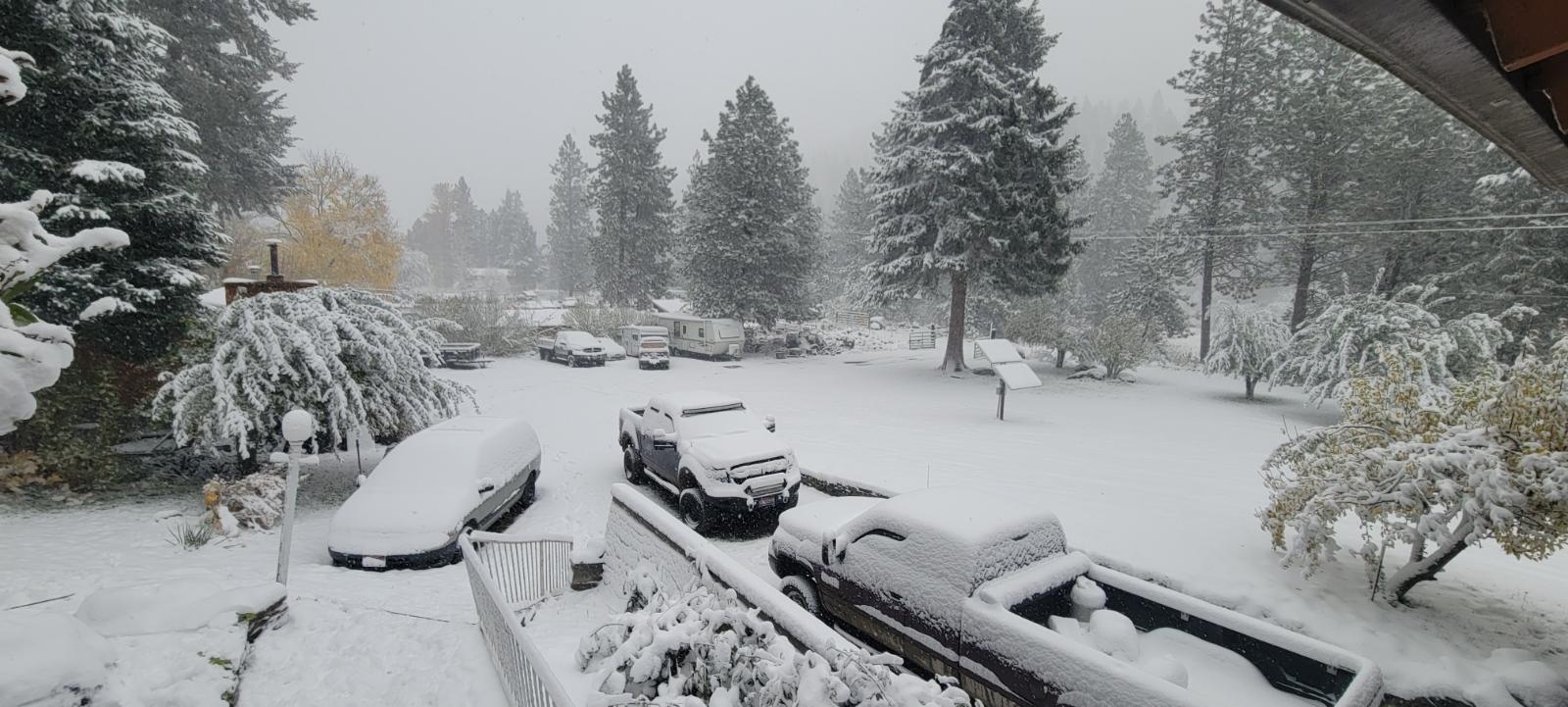
Actually the snow is a bit early for down here. Tonight its going to drop down to +17*F tonight and be cold. Still nothing much to panic about I was running in McCall ID in 2WD most of the day.
-
Do not use the stainless flex or stainless pipe. I had my past renter (Eileen's Son - Jacob) which managed to melt that stainless flex tube and drop the entire chimney liner back down inside the damper inside the chimney. Mark my current renter pull it all out and replaced the bottom half with all steel pipe and adjustable elbows and now its working again. Mark complains about being too hot now.
-
For me I don't think camping is going to occur till after winter is over being its been snowing here for most of the early morning hours. The RV you can see tucked in next to the tree in the yard.
-
Good Morning everyone. It officially winter in Idaho.
-
I wish... I fried my OBDLink LX series on a bad firmware update. I've not replaced it yet but plan on it soon.
-
No. The ABS is most likely a speed sensor. The misfire is going be separate. You could unplug the ABS module to see but I doubt it will change the misfire.
-
Heck it's just a day drive to get to Seattle WA from here in New Meadows ID.
-
Wow. Hang in there.
-
Older photo already done. Even Armor-All'ed the dash.
-
Yeah at this point I'm more or less gotta put Minnie away for the winter other than running to Riggins, ID maybe. It getting cold by Wednesday and will be +17*F for a evening temperature here. Yeah I'm moved over to running the diesel trucks. As for this scare of diesel running out I really doubt it will happen being Jet A and diesel are very close in design. Then Gasoline will always be produced with a by product of diesel. I'm stocked up here with food, supplies, and diesel fuel. Cold morning here at 27*F above but by Wednesday it will be starting out as low as +17*F. I see you all... Yup I can see who is on and where they come from...
 Damn internet is slow today really slow. 3 second video that takes 5 minutes to download enough to even see it happen. That is really cool!Back in the 70's the old 1976 Dodge Jamboree I had had the pin alignment for the wheels and the stem were required to be 180 out from each other and the pin ensured that it happened. That was back with steel wheels and 16.5 inch tires.