
Mopar1973Man
Owner
-
Joined
-
Last visited
Everything posted by Mopar1973Man
-
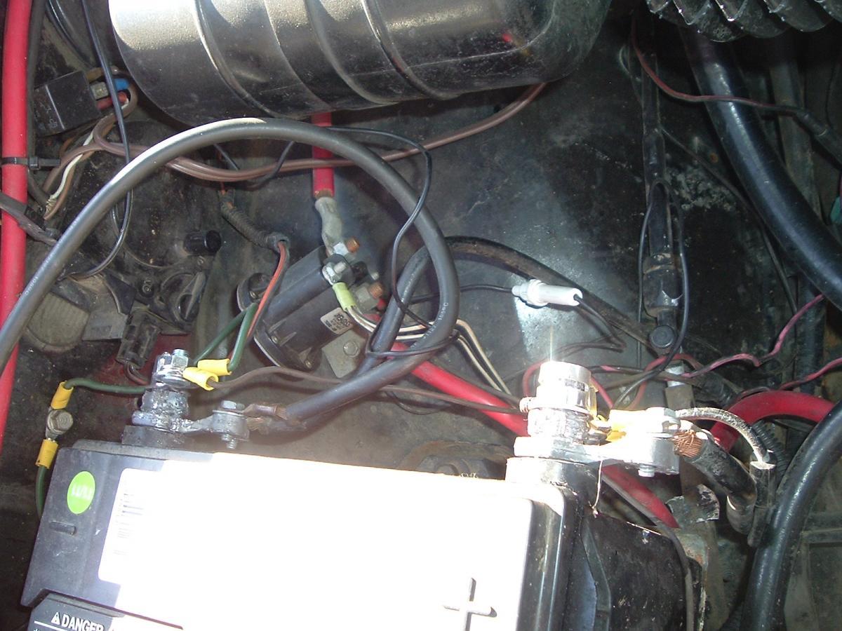
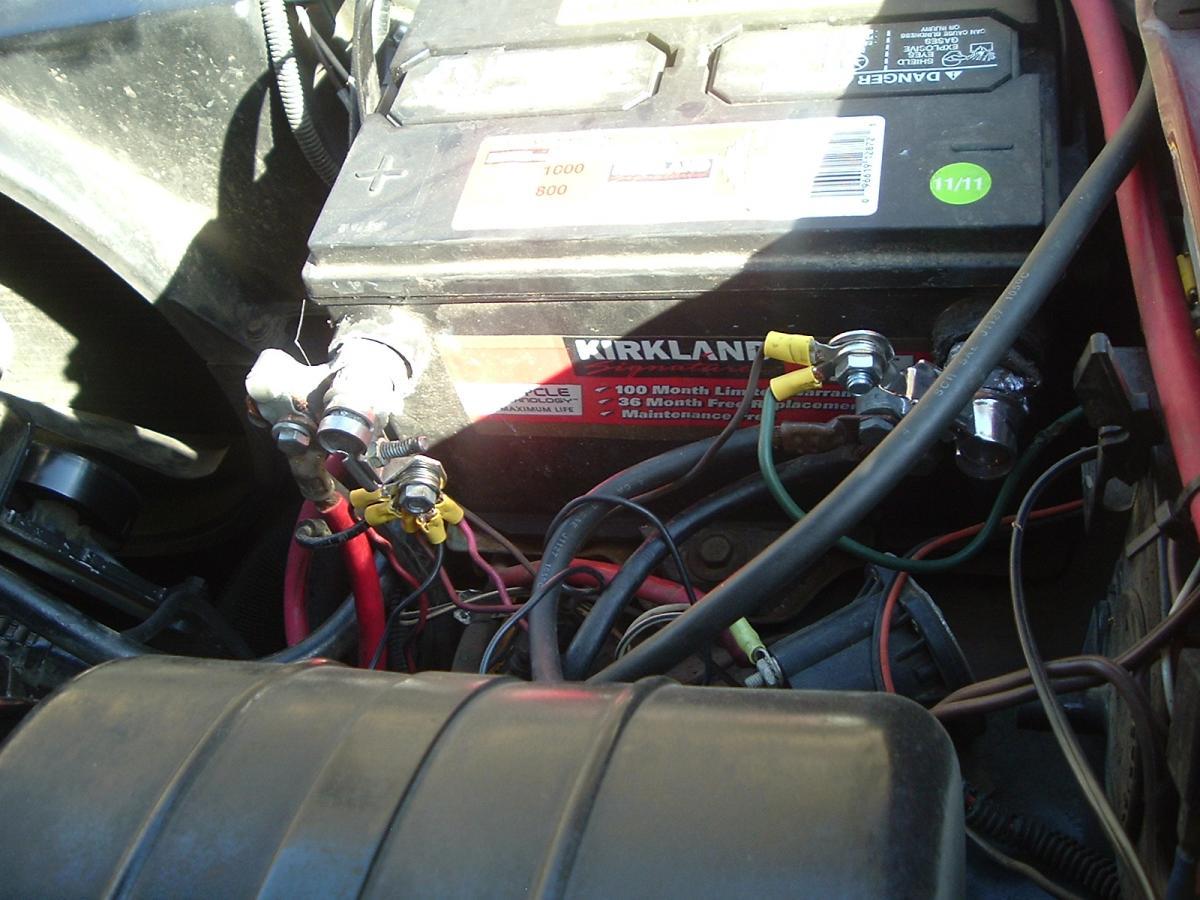
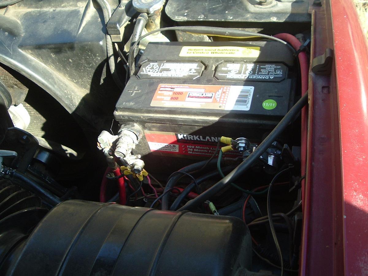
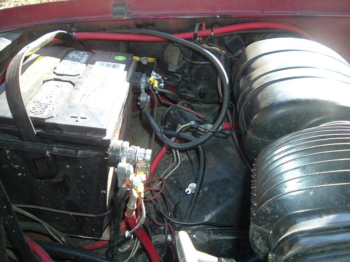
The owner works for the local EMS services so I'm assuming most of this was for light, radio, etc. No. I didn't go digging to figure it all out I just needed to re-crimp the master power lead for the truck to start. Nothing was fused every thing was hooked directly to the battery. Kind of scary.
-
Power is supplied for the Blue wire from Red/White wire 20A fuse. It most likely has some sort of switch action inside the PCM to cut the power when the key is off.
-
Yea. It only takes a bit a of dust and a bit of water to make mud. Then add a bit of road salt for oxidizer. Won't take long to eat the bolts away being the muds hold moisture and the road salt will continue to eat as long as the moisture is there. I had this very same problem YEARS ago on a 1972 Dodge Power Wagon and a U-bolt broke on me. I had to have custom made u-bolts to fix that old truck. After seeing that and seeing the axle design never changed I keep rinsing out the bottom plate. No problems.
-
Yea AirDog's are not what they once were. As for FASS I tend to still favor the twin filtered FASS over the single.
-
http://www.scangauge.com/support/upgrade/
-
Don't have that issue even with all the Idaho road salt used. When I wash my truck I take the extra time to rinse out under the body and flush out little places like the axle base where the u-bolts nut up.
-
Sad to say I've got a true first line SGII. Software version 1.00 there has been lots of updates. Free updates only if I can provide a receipt, but mine is long gone.
-
AirDog 150. Fuel pressure is 17-18 at idle and about 16 PSI at WOT.
-
In a pinch you could do a old school regulator but be warned it will not charge the same as the temperature controlled PCM. http://articles.mopar1973man.com/general-cummins/34-engine-system/134-voltage-regulator-mod
-
Field lead have to be tested unhooked. Because the alternator field is nothing more than a short. So now the blue wire should be 12V (POSITIVE) and the green wire should be a variable GROUND.
-
We had a gent have his Duramax towed in to the shop after filling it with gasoline. Yea he filled to full with gasoline in a diesel truck. Managed to drive just about half way home and it died. So went through the process of draining the fuel tank, disposing of the mixed fuel, and putting 10 gallons of fuel back in. Now Lindy ask me to change the filter. OMG! I'm looking at this going it going to be fun. Drain the filter and spun it off. Now how in the heck do you get it out. I finally figured if you drop it into the A arm on the passenger side then you can lay on the floor and lift it up and squeeze it back through the fender skirt. So now reverse process of installing. No fun at all. Then hearing about the price of a Duramax filter I about choked.
-
Most every knows I live up here in Idaho and most would think this far up north the summer would be rather mild. Well today when I left the shop the temp in the 1996 Dodge showed 108*F. Ugh... So what's every else seeing for temps?
-
Not that I know of. As far as I know its PSIa (atmosphere). Like I said it only a weird issue with the 24V Cummins.
-
I got a vehicle in the shop today that was a wiring nightmare. Easy fix but talk about "How not to wire a truck".
-
There is all kind of factor that could change it. But yeah I would have to say that's awfully weird to hit the same price.
-
Yes and no. From 0 to about 20 PSI its correct then slow there is a offset as you run outside the designed range of the sensor. As for SGII the newer software on the SGII does have boost gauge and do show correctly but again also has the same loss of accuracy as the Edge Juice. Outside the designed realm of the sensor.
-
I know the member is here on the site but who is the question.
-
You can try replacing the lift pump and see if you can gain some time from the VP44 but only the Good Lord knows if thee VP44 is damaged or not.
-
Check your fuses. Check your error codes there might be a clue there. Check your negative terminals. All grounds for the ECM, PCM and VP44 are in the battery cable there is no external body grounds.
-
Ummm... The PSG on top of the VP44 is overheating. Your WOT pressure needs to be above 14 PSI as a minimum. Idle doesn't count because the VP44 isn't under stress but WOT it being highly stressed electronics are creating more heat and the return flow to the tank is close at pressures below 14 PSI. So now you lost all cooling of the PSG.
-
Really common for fuel gauge to start showing higher level on the gauge when rheostat starts failing. Mine failed and was empty at 3/8 of a tank.
-
With all the changes it still doesn't do anything for long term storage of gasoline. As long as its stored in a vented tank then the fuel is going to go stale in a period of time. But air-tight container like my 55 gallon drum it will hold for a very very long time. Yes my bungs are o-ringed even and hold pressure or vacuum quite well.
-
Not sure why. But the SGII works just fine one all other vehicles. Just the 98.5 to 02 Dodge Cummins is skewed in value. I've not figured out why yet.
-
What your fuel pressure at WOT at highway speed?
-
Here is the diagnostic article. http://articles.mopar1973man.com/2nd-generation-24v-dodge-cummins/59-obdii-error-codes/163-p0222-idle-validation-both-low DTC P0222: IDLE VALIDATION SIGNALS BOTH LOW Monitor & Set Conditions Idle validation signals are monitored when ignition is on and engine is running. DTC P0222 may be stored if Engine Control Module (ECM) senses no voltage signal or the same voltage from Idle Validation Switch (IVS) No. 1 and IVS No. 2. DTC P0223 may be stored if ECM senses the same voltage from IVS No. 1 and IVS No. 2. Possible Causes Accelerator Pedal Position Switch (APPS) Idle Validation Switch (IVS) No. 2 Harness Short To Ground APPS IVS No. 2 Shorted To APPS Return Circuit APPS IVS No. 2 Shorted To APPS Sensor Ground IVS No. 2 Open Between APPS And ECM Harness Connectors APPS IVS No. 1 Shorted To APPS Sensor Ground APPS IVS No. 1 Shorted To APPS Return Circuit APPS IVS No. 1 Harness Short To Ground IVS No. 1 Open Between APPS And ECM Harness Connectors IVS No. 1 Circuit Open ECM Testing 1. Turn ignition off. Disconnect APPS harness connector. APPS is located on bracket, just above fuel injection pump. Check for poor connection/terminal contact at APPS harness connector. Repair as necessary. Start engine and allow engine to idle. Using DVOM, measure voltage between ground and terminal No. 6 (Brown/Orange wire) on APPS connector. This is the IVS No. 1 circuit. If voltage is greater than 4.5 volts, go to next step. If voltage is 5.5 volts or less, go to step 8 . 2. With engine idling, using DVOM, measure voltage between ground and terminal No. 2 (Light Green/Dark Blue wire) on APPS harness connector. This is the IVS No. 2 circuit. If voltage is 4.5 volts or less, go to next step. If voltage is greater than 4.5 volts, test is complete. 3. Turn ignition off. Check for continuity between ground and terminal No. 2 (Light Green/Dark Blue wire) on APPS harness connector. If continuity exists, go to next step. If continuity does not exist, go to step 7 . 4. Ensure ignition is off and APPS harness connector is still disconnected. Disconnect ECM harness connector. ECM is located on driver's side of engine, just in front of fuel transfer pump and contains a 50-pin connector. Check for continuity between ground and terminal No. 2 (Light Green/Dark Blue wire) on APPS harness connector. If continuity exists, repair short to ground in Light Green/Dark Blue wire between APPS and ECM. If continuity does not exist, go to next step. 5. Ensure ignition is off. Ensure APPS harness connector and ECM harness connector are still disconnected. Check for continuity between terminal No. 2 (Light Green/Dark Blue wire) and terminal No. 4 (Black/Yellow wire) on APPS harness connector. If continuity exists, repair short between Light Green/Dark Blue wire and Black/Yellow wire. If continuity does not exist, go to next step. 6. Ensure APPS harness connector and ECM harness connector are still disconnected. Check for continuity between terminal No. 2 (Light Green/Dark Blue wire) and terminal No. 1 (Black/Light Blue wire) on APPS harness connector. If continuity exists, repair short between Light Green/Dark Blue wire and Black/Light Blue wire. If continuity does not exist, replace and program the ECM. See appropriate REMOVAL, OVERHAUL & INSTALLATION article. 7. Ensure ignition is off and APPS harness connector is still disconnected. Disconnect ECM harness connector. ECM is located on driver's side of engine, just in front of fuel transfer pump and contains a 50-pin connector. Check continuity of Light Green/Dark Blue wire between terminal No. 2 on APPS harness connector and terminal No. 16 on ECM harness connector. If continuity exists, test is complete. If continuity does not exist, repair open in Light Green/Dark Blue wire between APPS and ECM. 8. Turn ignition off. Ensure APPS harness connector is still disconnected. Check for continuity between ground and terminal No. 6 (Brown/Orange wire) on APPS harness connector. If continuity exists, go to next step. If continuity does not exist, go to step 12 . 9. Ensure ignition is off and APPS harness connector is still disconnected. Disconnect ECM harness connector. ECM is located on driver's side of engine, just in front of fuel transfer pump and contains a 50- pin connector. Check for poor connection/terminal contact at ECM harness connector. Check for continuity between terminal No. 6 (Brown/Orange wire) and terminal No. 1 (Black/Light Blue wire) on APPS harness connector. If continuity exists, repair short between Brown/Orange wire and Black/Light Blue wire. If continuity does not exist, go to next step. 10. Ensure APPS harness connector and ECM harness connector are still disconnected. Check for continuity between terminal No. 6 (Brown/Orange wire) and terminal No. 4 (Black/Yellow wire) on APPS harness connector. If continuity exists, repair short between Brown/Orange wire and Black/Yellow wire. If continuity does not exist, go to next step. 11. Ensure APPS harness connector and ECM harness connector are still disconnected. Check for continuity between ground and terminal No. 6 (Brown/Orange wire) on APPS harness connector. If continuity exists, repair short to ground in Brown/Orange wire. If continuity does not exist, test is complete. 12. Ensure ignition is off and APPS harness connector is still disconnected. Disconnect ECM harness connector. ECM is located on driver's side of engine, just in front of fuel transfer pump and contains a 50-pin connector. Check for poor connection/terminal contact at ECM harness connector. Repair as necessary. Check Brown/Orange wire for continuity between terminal No. 6 on APPS harness connector and terminal No. 1 on ECM harness connector. If continuity exists, test is complete. If continuity does not exist, repair open in Brown/Orange wire between APPS and ECM.