


Mopar1973Man
Owner
-
Joined
-
Last visited
Everything posted by Mopar1973Man
-
I'm curious too. Scratchging my head the only other vendor I use but don't exactly support is RockAuto... (Guessin')
-
Yup I kind of figured. The high idle and the engine load of ZERO. Again the pop pressure was so low it could not cut enough to idle slow enough. Like I said go to someone like @dieselautopower for injectors and then you can specify anything you wish. Size, nozzle type (VCO vs. SAC), pop pressure changes, etc. But all in all the injectors are built in house and pop tested and flow match before leaving.
-
Something is wrong even here being the engine load is zero. Even all the trucks I've worked on always showed at least 7% to 15% depending on size and pop pressure. Even my 2002 it idles at 13% still to this day. Now you mention Bosch RV275 injectors these are some that I don't suggest because they are 6 random injectors pulled and boxed up. There is no flow matching or pop testing to bring them into small percentage of margin. I typically would rather suggest 50 HP custom made at least you know all the injectors are tested, flow match and within small percentage of error..
-
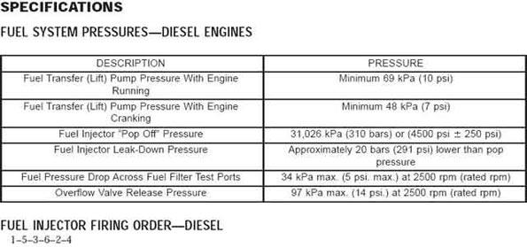
Ok... So the APPS is replaced and now lets move on to other topics. So I guess you have factory stock injectors yet? How many miles on the injectors? Another way to look at this problem is hook up a live data tool with the truck warmed up complete and monitor the engine load if its 3% or lower to ZERO then your injectors are wore out and the ECM is attempting to cut fuel as deep as it can but since the injectors are popping too early and there is no longer any more control the ECM can try to pull the RPM's down. Second way to test this is to remove all six injectors and have the injectors pop tested typically about $15 a injector about $90 to test all six injectors. Solution to this is replacing all six injectors. Like I said you can verify with a live data tool and check the engine load at idle warmed up. Pop pressures in Bar (PSI) 280 (4,061) and lower - Typically the idle is rising and the Engine load is zero. 293 (4,249) - Bottom end of allowed by Dodge FSM 300 (4,351) - Some performance injectors are popped this low to aid to flow. 305 (4,423) - Fairly common pop pressure used by performance injectors. 310 (4,500) - Stock Injector pressure 320 (4,641) - Personally what I run on my truck to aid in fine mist spray and MPG. 327 (4,742) - High end of Dodge FSM allowed pop pressure 330 (4,786) and higher - Possible hard starting in the winter time.
-
So even having once doesn't guarantee your immune to the virus. Then on top you both got 3 rounds of the vaccines that shows it doesn't work at all. Taken quite awhile getting there but at least you have your radiator and it is undamaged.
-
Normal. Even "Beast" runs as high as 1,100 RPM's as you clutched in and rolling to a stop and then closer to a stop it drops down on the idle software to 800 RPM. This is a manual set up I'm talking about but since you don't have any info in your signature on the truck its a guess. When the APPS sensor is in the IDLE MODE (Idle Validation Switch) then the ECM is in full control of the idle speeds as it rolling. Now if the APPS sensor is having issues and stuck in THROTTLING MODE then the idle could be inherently high because the ECM can't reach the idle mode. Have you adjusted voltage on the APPS sensor? (Hopefully not... ) This explains much much more about the APPS sensor.
-
I'm always impressed with old American Muscle of that time. Even thought it was a little 6 cylinder it nice to see engines once again without all the computers and wiring.
-
So what are you planning on doing?
-
Now you might understand why I bailed out of Microsoft PCs and went to the Dark Side with Ubuntu & CentOS Linux...
-
Always loved the old American truck and cars. I look at the simple design of that little Inline Six Cylinder engine. No computers, no sensors, no error codes, just engine. I'm old enough to have some of the beauties that time has forgotten by now... Then I wake up open a modern day hood and all I want to do is cry and slam the hood down.
-
Not really... Like I've mention once in the past post as you add boost pressure and figure the cylinder pressures could be as high as 1,100 PSI. Compression isn't going to make any huge difference, consider the engine alone create 400 to 450 on a compression test. Then add 30 PSI of boost on top and reach 1,100 PSI roughly. There will be enough temperature to light off even low cetane. But what compression does effect is the flywheel torque value. Lower compression engines can run more boost pressure safely vs. high compression engine. Consider the early Ford IDI was 21:1 compression ratio, with no turbo.
-
Seal kit to what? Steering box? Vacuum pump?So true. So what have you been up too? You have been quiet too. Hmmm?Well the only other fuel related item is VP44 but that getting pricey for gambling.APPS sensor isn't going to make a miss for sure. That miss I would start with injectors first either replace them or have your current ones pop tested. Can you check for error codes please? @2000CumminsyessirP0206 - Fuel Injector 6 Circuit / Open Theory of Operation The Powertrain Control Module (PCM) actuates the solenoid in the Fuel Injector causing the needle valve to rise and fuel flows through the spray holes in the nozzle tip into the combustion chamber. The PCM has a common internal driver circuit to all three Fuel Injectors on each bank. If any injector circuit on a given bank has a short to ground or a short to voltage, a DTC will be set for all three Fuel Injectors on that bank. Fuel Injectors 1,2,3 are grouped together on bank 1. Fuel Injectors 4,5,6 are grouped together on bank 2. The MIL will illuminate immediately after the diagnostic runs and fails twice. During this time the customer may experience engine surge or stumble. The MIL lamp will turn off once the diagnostic runs and passes in four consecutive drive cycles. When Monitored: Every 20 milliseconds when the ignition is on. Set Condition: When the Fuel Injector current falls below a calibrated threshold. Possible Causes HIGH SIDE DRIVER CIRCUIT OPEN/HIGH RESISTANCE LOW SIDE DRIVER CIRCUIT OPEN/HIGH RESISTANCE HIGH SIDE DRIVER CIRCUIT SHORTED TO GROUND LOW SIDE DRIVER CIRCUIT SHORTED TO GROUND HIGH SIDE DRIVER CIRCUIT SHORTED TO VOLTAGE LOW SIDE DRIVER CIRCUIT SHORTED TO VOLTAGE DRIVER CIRCUITS SHORTED TOGETHER VALVE COVER PASS THROUGH HARNESS FUEL INJECTOR POWERTRAIN CONTROL MODULE (PCM)– ONLY WHEN ALL INJECTOR WIRING TESTS GOOD AND ALL 3 DTCS ON THE BANK ARE ACTIVE Always perform the Pre-Diagnostic Troubleshooting procedure before proceeding. (Refer to 28 - DTC- Based Diagnostics/MODULE, Powertrain Control (PCM) - Standard Procedure). Diagnostic Test 1. ACTIVE DTC 1. Ignition on, engine not running. 2. With the scan tool check for active DTCs. Is the DTC active? Yes • Go To 2 No • Perform the INTERMITTENT CONDITION diagnostic procedure. (Refer to 28 - DTC-Based Diagnostics/MODULE, Powertrain Control (PCM) - Standard Procedure). 2. CHECK EACH FUEL INJECTOR CIRCUIT FOR AN OPEN/HIGH RESISTANCE 1. Turn the ignition off. 2. Disconnect the PCM C1 harness connector. 3. Measure the resistance between the: • (K614) Fuel Injector 4 High Side Driver circuit and the (K14) Fuel Injector 4 Low Side Driver circuit at the PCM C1 harness connector. • (K38) Fuel Injector 5 High Side Driver circuit and the (K638) Fuel Injector 5 Low Side Driver circuit at the PCM C1 harness connector. • (K658) Fuel Injector 6 High Side Driver circuit and the (K58) Fuel Injector 6 Low Side Driver circuit at the PCM C1 harness connector. NOTE: Be sure to zero out the Ohm meter prior to checking the Fuel Injector circuit. Resistance reading should be between 0-1 Ohm. Is the resistance between 0-1 Ohm for each Fuel Injector circuit? Yes • Go To 3 No • Go To 8 3. CHECK EACH FUEL INJECTOR CIRCUIT FOR A SHORT TO GROUND 1. Measure the resistance between ground and the: • (K614) Fuel Injector 4 High Side Driver circuit at the PCM C1 harness connector. • (K38) Fuel Injector 5 High Side Driver circuit at the PCM C1 harness connector. • (K658) Fuel Injector 6 High Side Driver circuit at the PCM C1 harness connector. NOTE: There should be no continuity between the circuit and ground. Is the resistance below 10k Ohms on any injector circuits? Yes • Go To 12 No • Go To 4 4. CHECKING FOR INJECTOR CONTROL CIRCUITS SHORTED TOGETHER 1. Disconnect the valve cover pass through wires at each Bank 2 Fuel Injector terminal. NOTE: Do not disconnect the valve cover pass through harness from the engine harness. 2. At the PCM C1 harness connector, measure the resistance between ALL (Bank 2) Low AND High Side Control circuits: K614(High 4), K14(Low 4), K38(High 5), K638(Low 5), K658(High 6), and K58(Low 6). Is the resistance below 10k ohms between any Injector Control circuits? Yes • Repair the Injector Control circuits that are shorted together. • Perform the POWERTRAIN VERIFICATION TEST - 6.7L. (Refer to 28 - DTC-Based Diagnostics/MODULE, Powertrain Control (PCM) - Standard Procedure). No • Go To 5 5. ISOLATE CYLINDER 4 FUEL INJECTOR 1. Reconnect the PCM C1 harness connector to the PCM. 2. Leave the valve cover pass through wires disconnected at the Cylinder 4 Fuel Injector terminals. 3. Reconnect the valve cover pass through wires at the Cylinder 5 and 6 Fuel Injector terminals. NOTE: Torque the Injector terminal nuts to 8.8 in-lbs. 4. Place electrical tape on the ends of the disconnected valve cover pass through wires to prevent the Injector terminal nuts from coming in contact with each other or the engine block. 5. Place the valve cover on the engine. NOTE: It is not necessary to bolt the valve cover in place. 6. Ignition on, engine not running. 7. With the scan tool, erase all DTCs. 8. Start the engine and let idle for 1 minute. 9. Ignition on, engine not running. 10. With the scan tool, read DTCs. Are multiple bank 2 injector circuit DTCs (P0204, P0205, P0206) active? Yes • Go To 6 No • Replace the Cylinder 4 Fuel Injector in accordance with the Service Information.(Refer to 14 - Fuel System/Fuel Inspection/INJECTOR(S) , Fuel/Removal) • Perform the POWERTRAIN VERIFICATION TEST - 6.7L. (Refer to 28 - DTC-Based Diagnostics/MODULE, Powertrain Control (PCM) - Standard Procedure). 6. ISOLATE CYLINDER 5 FUEL INJECTOR 1. Reconnect the valve cover pass through wires at the Cylinder 4 Fuel Injector terminals. NOTE: Torque the Injector terminal nuts to 8.8 in-lbs. 2. Disconnect the valve cover pass through wires at the Cylinder 5 Fuel Injector terminals. 3. Place electrical tape on the ends of the disconnected valve cover pass through wires to prevent the injector terminal nuts from coming in contact with each other or the engine block. 4. Place the valve cover on the engine. NOTE: It is not necessary to bolt the valve cover in place. 5. Ignition on, engine not running. 6. With the scan tool, erase all DTCs. 7. Start the engine and let idle for 1 minute. 8. Ignition on, engine not running. 9. With the scan tool, read DTCs. Are multiple bank 2 injector circuit DTCs (P0204, P0205, P0206) active? Yes • Go To 7 No • Replace the Cylinder 5 Fuel Injector in accordance with the Service Information.(Refer to 14 - Fuel System/Fuel Inspection/INJECTOR(S) , Fuel/Removal) • Perform the POWERTRAIN VERIFICATION TEST - 6.7L. (Refer to 28 - DTC-Based Diagnostics/MODULE, Powertrain Control (PCM) - Standard Procedure). 7. ISOLATE CYLINDER 6 FUEL INJECTOR 1. Reconnect the valve cover pass through wires at the cylinder 5 fuel injector terminals. NOTE: Torque the injector terminal nuts to 8.8 in-lbs. 2. Disconnect the valve cover pass through wires at the cylinder 6 fuel injector terminals. 3. Place electrical tape on the ends of the disconnected valve cover pass through wires to prevent the injector terminal nuts from coming in contact with each other or the engine block. 4. Place the valve cover on the engine. NOTE: It is not necessary to bolt the valve cover in place. 5. Ignition on, engine not running. 6. With the scan tool, erase all DTCs. 7. Start the engine and let idle for 1 minute. 8. Ignition on, engine not running. 9. With the scan tool, read DTCs. Are multiple bank 2 injector circuit DTCs (P0204, P0205, P0206) active? Yes • Replace the Powertrain Control Module in accordance with the Service Information. • Perform the POWERTRAIN VERIFICATION TEST - 6.7L. (Refer to 28 - DTC-Based Diagnostics/MODULE, Powertrain Control (PCM) - Standard Procedure). No • Replace the Cylinder 6 Fuel Injector in accordance with the Service Information.(Refer to 14 - Fuel System/Fuel Inspection/INJECTOR(S) , Fuel/Removal) • Perform the POWERTRAIN VERIFICATION TEST - 6.7L. (Refer to 28 - DTC-Based Diagnostics/MODULE, Powertrain Control (PCM) - Standard Procedure). 8. CHECK THE VALVE COVER PASS THROUGH HARNESS CIRCUIT NOTE: Perform the following tests on the Fuel Injector circuit which was faulty. 1. Disconnect the Valve Cover Pass Through harness connector. 2. Measure the resistance between the Low Side Driver circuit and the High Side Driver circuit at the Valve Cover Pass Through connector terminals. NOTE: Be sure to zero the Ohm meter prior to checking the Fuel Injector circuit. Is the resistance between 0-1 Ohm? Yes • Go To 9 No • Go To 11 9. CHECK THE HIGH SIDE CIRCUITS IN ENGINE HARNESS 1. Measure the resistance of the High Side Driver circuit between the Valve Cover Pass Through harness connector and the PCM C1 harness connector. NOTE: Be sure to zero the Ohm meter prior to checking the Fuel Injector circuit. Is the resistance between 0-1 Ohm? Yes • Go To 10 No • Repair the High Side Driver circuit for an open or high resistance. • Perform the POWERTRAIN VERIFICATION TEST - 6.7L. (Refer to 28 - DTC-Based Diagnostics/MODULE, Powertrain Control (PCM) - Standard Procedure). 10. CHECK THE LOW SIDE CIRCUITS IN ENGINE HARNESS 1. Measure the resistance of the Low Side Driver circuit between the Valve Cover Pass Through harness connector and the PCM C1 harness connector. NOTE: Be sure to zero the Ohm meter prior to checking the Fuel Injector circuit. Is the resistance between 0-1 Ohm? Yes • Test complete. Perform the INTERMITTENT CONDITION diagnostic procedure. (Refer to 28 - DTC- Based Diagnostics/MODULE, Powertrain Control (PCM) - Standard Procedure). No • Repair the Low Side Driver circuit for an open or high resistance. • Perform the POWERTRAIN VERIFICATION TEST - 6.7L. (Refer to 28 - DTC-Based Diagnostics/MODULE, Powertrain Control (PCM) - Standard Procedure). 11. CHECK FUEL INJECTORS 1. Disconnect all bank 2 Fuel Injector wires at the Fuel Injectors. 2. Measure the resistance across the terminals at the Fuel Injector. NOTE: Be sure to zero the Ohm meter prior to checking the Fuel Injector circuit. Is the resistance between 0-1 Ohm? Yes • Replace the Valve Cover Pass Through harness in accordance with the service information. • Perform the POWERTRAIN VERIFICATION TEST - 6.7L. (Refer to 28 - DTC-Based Diagnostics/MODULE, Powertrain Control (PCM) - Standard Procedure). No • Replace the Fuel Injector in accordance with the Service Information.(Refer to 14 - Fuel System/Fuel Inspection/INJECTOR(S) , Fuel/Removal) • Perform the POWERTRAIN VERIFICATION TEST - 6.7L. (Refer to 28 - DTC-Based Diagnostics/MODULE, Powertrain Control (PCM) - Standard Procedure). 12. CHECK FOR THE DRIVER CIRCUITS SHORTED TOGETHER 1. Disconnect all bank 2 Fuel Injector wires at the Fuel Injectors. 2. Measure the resistance between all bank 2 Driver circuits at the PCM C1 harness connector. Is the resistance below 10k Ohms between any circuits? Yes • Go To 13 No • Go To 14 13. CHECK THE VALVE COVER PASS THROUGH HARNESS CIRCUITS 1. Disconnect the Valve Cover Pass Through harness connector. 2. Measure the resistance between all bank 2 Driver circuits of the Valve Cover Pass Through connector terminals. Is the resistance below 10k Ohms between any circuits? Yes • Replace the Valve Cover Pass Through harness in accordance with the service information. • Perform the POWERTRAIN VERIFICATION TEST - 6.7L. (Refer to 28 - DTC-Based Diagnostics/MODULE, Powertrain Control (PCM) - Standard Procedure). No • Repair the short between the bank 2 Driver circuits in the engine harness. • Perform the POWERTRAIN VERIFICATION TEST - 6.7L. (Refer to 28 - DTC-Based Diagnostics/MODULE, Powertrain Control (PCM) - Standard Procedure). 14. CHECK THE HIGH SIDE DRIVER CIRCUIT FOR A SHORT TO GROUND NOTE: Perform the following tests on the Fuel Injector circuit which was faulty. 1. Disconnect the Valve Cover Pass Through harness connector . 2. Measure the resistance between ground and the High Side Driver circuit at the PCM C1 connector. Is the resistance below 10k Ohms? Yes • Repair the High Side Driver circuit for a short to ground. • Perform the POWERTRAIN VERIFICATION TEST - 6.7L. (Refer to 28 - DTC-Based Diagnostics/MODULE, Powertrain Control (PCM) - Standard Procedure). No • Go To 15 15. CHECK THE LOW SIDE DRIVER CIRCUIT FOR A SHORT TO GROUND 1. Measure the resistance between ground and the Low Side Driver circuit at the PCM C1 connector. Is the resistance below 10k Ohms? Yes • Repair the Low Side Driver circuit for a short to ground. • Perform the POWERTRAIN VERIFICATION TEST - 6.7L. (Refer to 28 - DTC-Based Diagnostics/MODULE, Powertrain Control (PCM) - Standard Procedure). No • Go To 16 16. CHECK THE FUEL INJECTORS 1. Measure the resistance between ground and one of the Fuel Injector terminals. Is the resistance below 10k Ohms? Yes • Replace the Fuel Injector in accordance with the Service Information.(Refer to 14 - Fuel System/Fuel Inspection/INJECTOR(S) , Fuel/Removal) • Perform the POWERTRAIN VERIFICATION TEST - 6.7L. (Refer to 28 - DTC-Based Diagnostics/MODULE, Powertrain Control (PCM) - Standard Procedure). No • Replace the Valve Cover Pass Through harness in accordance with the service information. • Perform the POWERTRAIN VERIFICATION TEST - 6.7L. (Refer to 28 - DTC-Based Diagnostics/MODULE, Powertrain Control (PCM) - Standard Procedure).P0205 - Fuel Injector 5 Circuit / Open Theory of Operation The Powertrain Control Module (PCM) actuates the solenoid in the Fuel Injector causing the needle valve to rise and fuel flows through the spray holes in the nozzle tip into the combustion chamber. The PCM has a common internal driver circuit to all three Fuel Injectors on each bank. If any injector circuit on a given bank has a short to ground or a short to voltage, a DTC will be set for all three Fuel Injectors on that bank. Fuel Injectors 1,2,3 are grouped together on bank 1. Fuel Injectors 4,5,6 are grouped together on bank 2. The MIL will illuminate immediately after the diagnostic runs and fails twice. During this time the customer may experience engine surge or stumble. The MIL lamp will turn off once the diagnostic runs and passes in four consecutive drive cycles. When Monitored: Every 20 milliseconds when the ignition is on. Set Condition: When the Fuel Injector current falls below a calibrated threshold. Possible Causes HIGH SIDE DRIVER CIRCUIT OPEN/HIGH RESISTANCE LOW SIDE DRIVER CIRCUIT OPEN/HIGH RESISTANCE HIGH SIDE DRIVER CIRCUIT SHORTED TO GROUND LOW SIDE DRIVER CIRCUIT SHORTED TO GROUND HIGH SIDE DRIVER CIRCUIT SHORTED TO VOLTAGE LOW SIDE DRIVER CIRCUIT SHORTED TO VOLTAGE DRIVER CIRCUITS SHORTED TOGETHER VALVE COVER PASS THROUGH HARNESS FUEL INJECTOR POWERTRAIN CONTROL MODULE (PCM)– ONLY WHEN ALL INJECTOR WIRING TESTS GOOD AND ALL 3 DTCS ON THE BANK ARE ACTIVE Always perform the Pre-Diagnostic Troubleshooting procedure before proceeding. (Refer to 28 - DTC-Based Diagnostics/MODULE, Powertrain Control (PCM) - Standard Procedure). Diagnostic Test 1. ACTIVE DTC 1. Ignition on, engine not running. 2. With the scan tool check for active DTCs. Is the DTC active? Yes • Go To 2 No • Perform the INTERMITTENT CONDITION diagnostic procedure. (Refer to 28 - DTC-Based Diagnostics/MODULE, Powertrain Control (PCM) - Standard Procedure). 2. CHECK EACH FUEL INJECTOR CIRCUIT FOR AN OPEN/HIGH RESISTANCE 1. Turn the ignition off. 2. Disconnect the PCM C1 harness connector. 3. Measure the resistance between the: • (K614) Fuel Injector 4 High Side Driver circuit and the (K14) Fuel Injector 4 Low Side Driver circuit at the PCM C1 harness connector. • (K38) Fuel Injector 5 High Side Driver circuit and the (K638) Fuel Injector 5 Low Side Driver circuit at the PCM C1 harness connector. • (K658) Fuel Injector 6 High Side Driver circuit and the (K58) Fuel Injector 6 Low Side Driver circuit at the PCM C1 harness connector. NOTE: Be sure to zero out the Ohm meter prior to checking the Fuel Injector circuit. Resistance reading should be between 0-1 Ohm. Is the resistance between 0-1 Ohm for each Fuel Injector circuit? Yes • Go To 3 No • Go To 8 3. CHECK EACH FUEL INJECTOR CIRCUIT FOR A SHORT TO GROUND 1. Measure the resistance between ground and the: • (K614) Fuel Injector 4 High Side Driver circuit at the PCM C1 harness connector. • (K38) Fuel Injector 5 High Side Driver circuit at the PCM C1 harness connector. • (K658) Fuel Injector 6 High Side Driver circuit at the PCM C1 harness connector. NOTE: There should be no continuity between the circuit and ground. Is the resistance below 10k Ohms on any injector circuits? Yes • Go To 12 No • Go To 4 4. CHECKING FOR INJECTOR CONTROL CIRCUITS SHORTED TOGETHER 1. Disconnect the valve cover pass through wires at each Bank 2 Fuel Injector terminal. NOTE: Do not disconnect the valve cover pass through harness from the engine harness. 2. At the PCM C1 harness connector, measure the resistance between ALL (Bank 2) Low AND High Side Control circuits: K614(High 4), K14(Low 4), K38(High 5), K638(Low 5), K658(High 6), and K58(Low 6). Is the resistance below 10k ohms between any Injector Control circuits? Yes • Repair the Injector Control circuits that are shorted together. • Perform the POWERTRAIN VERIFICATION TEST - 6.7L. (Refer to 28 - DTC-Based Diagnostics/MODULE, Powertrain Control (PCM) - Standard Procedure). No • Go To 5 5. ISOLATE CYLINDER 4 FUEL INJECTOR 1. Reconnect the PCM C1 harness connector to the PCM. 2. Leave the valve cover pass through wires disconnected at the Cylinder 4 Fuel Injector terminals. 3. Reconnect the valve cover pass through wires at the Cylinder 5 and 6 Fuel Injector terminals. NOTE: Torque the Injector terminal nuts to 8.8 in-lbs. 4. Place electrical tape on the ends of the disconnected valve cover pass through wires to prevent the Injector terminal nuts from coming in contact with each other or the engine block. 5. Place the valve cover on the engine. NOTE: It is not necessary to bolt the valve cover in place. 6. Ignition on, engine not running. 7. With the scan tool, erase all DTCs. 8. Start the engine and let idle for 1 minute. 9. Ignition on, engine not running. 10. With the scan tool, read DTCs. Are multiple bank 2 injector circuit DTCs (P0204, P0205, P0206) active? Yes • Go To 6 No • Replace the Cylinder 4 Fuel Injector in accordance with the Service Information.(Refer to 14 - Fuel System/Fuel Inspection/INJECTOR(S) , Fuel/Removal) • Perform the POWERTRAIN VERIFICATION TEST - 6.7L. (Refer to 28 - DTC-Based Diagnostics/MODULE, Powertrain Control (PCM) - Standard Procedure). 6. ISOLATE CYLINDER 5 FUEL INJECTOR 1. Reconnect the valve cover pass through wires at the Cylinder 4 Fuel Injector terminals. NOTE: Torque the Injector terminal nuts to 8.8 in-lbs. 2. Disconnect the valve cover pass through wires at the Cylinder 5 Fuel Injector terminals. 3. Place electrical tape on the ends of the disconnected valve cover pass through wires to prevent the injector terminal nuts from coming in contact with each other or the engine block. 4. Place the valve cover on the engine. NOTE: It is not necessary to bolt the valve cover in place. 5. Ignition on, engine not running. 6. With the scan tool, erase all DTCs. 7. Start the engine and let idle for 1 minute. 8. Ignition on, engine not running. 9. With the scan tool, read DTCs. Are multiple bank 2 injector circuit DTCs (P0204, P0205, P0206) active? Yes • Go To 7 No • Replace the Cylinder 5 Fuel Injector in accordance with the Service Information.(Refer to 14 - Fuel System/Fuel Inspection/INJECTOR(S) , Fuel/Removal) • Perform the POWERTRAIN VERIFICATION TEST - 6.7L. (Refer to 28 - DTC-Based Diagnostics/MODULE, Powertrain Control (PCM) - Standard Procedure). 7. ISOLATE CYLINDER 6 FUEL INJECTOR 1. Reconnect the valve cover pass through wires at the cylinder 5 fuel injector terminals. NOTE: Torque the injector terminal nuts to 8.8 in-lbs. 2. Disconnect the valve cover pass through wires at the cylinder 6 fuel injector terminals. 3. Place electrical tape on the ends of the disconnected valve cover pass through wires to prevent the injector terminal nuts from coming in contact with each other or the engine block. 4. Place the valve cover on the engine. NOTE: It is not necessary to bolt the valve cover in place. 5. Ignition on, engine not running. 6. With the scan tool, erase all DTCs. 7. Start the engine and let idle for 1 minute. 8. Ignition on, engine not running. 9. With the scan tool, read DTCs. Are multiple bank 2 injector circuit DTCs (P0204, P0205, P0206) active? Yes • Replace the Powertrain Control Module in accordance with the Service Information. • Perform the POWERTRAIN VERIFICATION TEST - 6.7L. (Refer to 28 - DTC-Based Diagnostics/MODULE, Powertrain Control (PCM) - Standard Procedure). No • Replace the Cylinder 6 Fuel Injector in accordance with the Service Information.(Refer to 14 - Fuel System/Fuel Inspection/INJECTOR(S) , Fuel/Removal) • Perform the POWERTRAIN VERIFICATION TEST - 6.7L. (Refer to 28 - DTC-Based Diagnostics/MODULE, Powertrain Control (PCM) - Standard Procedure). 8. CHECK THE VALVE COVER PASS THROUGH HARNESS CIRCUIT NOTE: Perform the following tests on the Fuel Injector circuit which was faulty. 1. Disconnect the Valve Cover Pass Through harness connector. 2. Measure the resistance between the Low Side Driver circuit and the High Side Driver circuit at the Valve Cover Pass Through connector terminals. NOTE: Be sure to zero the Ohm meter prior to checking the Fuel Injector circuit. Is the resistance between 0-1 Ohm? Yes • Go To 9 No • Go To 11 9. CHECK THE HIGH SIDE CIRCUITS IN ENGINE HARNESS 1. Measure the resistance of the High Side Driver circuit between the Valve Cover Pass Through harness connector and the PCM C1 harness connector. NOTE: Be sure to zero the Ohm meter prior to checking the Fuel Injector circuit. Is the resistance between 0-1 Ohm? Yes • Go To 10 No • Repair the High Side Driver circuit for an open or high resistance. • Perform the POWERTRAIN VERIFICATION TEST - 6.7L. (Refer to 28 - DTC-Based Diagnostics/MODULE, Powertrain Control (PCM) - Standard Procedure). 10. CHECK THE LOW SIDE CIRCUITS IN ENGINE HARNESS 1. Measure the resistance of the Low Side Driver circuit between the Valve Cover Pass Through harness connector and the PCM C1 harness connector. NOTE: Be sure to zero the Ohm meter prior to checking the Fuel Injector circuit. Is the resistance between 0-1 Ohm? Yes • Test complete. Perform the INTERMITTENT CONDITION diagnostic procedure. (Refer to 28 - DTC- Based Diagnostics/MODULE, Powertrain Control (PCM) - Standard Procedure). No • Repair the Low Side Driver circuit for an open or high resistance. • Perform the POWERTRAIN VERIFICATION TEST - 6.7L. (Refer to 28 - DTC-Based Diagnostics/MODULE, Powertrain Control (PCM) - Standard Procedure). 11. CHECK FUEL INJECTORS 1. Disconnect all bank 2 Fuel Injector wires at the Fuel Injectors. 2. Measure the resistance across the terminals at the Fuel Injector. NOTE: Be sure to zero the Ohm meter prior to checking the Fuel Injector circuit. Is the resistance between 0-1 Ohm? Yes • Replace the Valve Cover Pass Through harness in accordance with the service information. • Perform the POWERTRAIN VERIFICATION TEST - 6.7L. (Refer to 28 - DTC-Based Diagnostics/MODULE, Powertrain Control (PCM) - Standard Procedure). No • Replace the Fuel Injector in accordance with the Service Information.(Refer to 14 - Fuel System/Fuel Inspection/INJECTOR(S) , Fuel/Removal) • Perform the POWERTRAIN VERIFICATION TEST - 6.7L. (Refer to 28 - DTC-Based Diagnostics/MODULE, Powertrain Control (PCM) - Standard Procedure). 12. CHECK FOR THE DRIVER CIRCUITS SHORTED TOGETHER 1. Disconnect all bank 2 Fuel Injector wires at the Fuel Injectors. 2. Measure the resistance between all bank 2 Driver circuits at the PCM C1 harness connector. Is the resistance below 10k Ohms between any circuits? Yes • Go To 13 No • Go To 14 13. CHECK THE VALVE COVER PASS THROUGH HARNESS CIRCUITS 1. Disconnect the Valve Cover Pass Through harness connector. 2. Measure the resistance between all bank 2 Driver circuits of the Valve Cover Pass Through connector terminals. Is the resistance below 10k Ohms between any circuits? Yes • Replace the Valve Cover Pass Through harness in accordance with the service information. • Perform the POWERTRAIN VERIFICATION TEST - 6.7L. (Refer to 28 - DTC-Based Diagnostics/MODULE, Powertrain Control (PCM) - Standard Procedure). No • Repair the short between the bank 2 Driver circuits in the engine harness. • Perform the POWERTRAIN VERIFICATION TEST - 6.7L. (Refer to 28 - DTC-Based Diagnostics/MODULE, Powertrain Control (PCM) - Standard Procedure). 14. CHECK THE HIGH SIDE DRIVER CIRCUIT FOR A SHORT TO GROUND NOTE: Perform the following tests on the Fuel Injector circuit which was faulty. 1. Disconnect the Valve Cover Pass Through harness connector . 2. Measure the resistance between ground and the High Side Driver circuit at the PCM C1 connector. Is the resistance below 10k Ohms? Yes • Repair the High Side Driver circuit for a short to ground. • Perform the POWERTRAIN VERIFICATION TEST - 6.7L. (Refer to 28 - DTC-Based Diagnostics/MODULE, Powertrain Control (PCM) - Standard Procedure). No • Go To 15 15. CHECK THE LOW SIDE DRIVER CIRCUIT FOR A SHORT TO GROUND 1. Measure the resistance between ground and the Low Side Driver circuit at the PCM C1 connector. Is the resistance below 10k Ohms? Yes • Repair the Low Side Driver circuit for a short to ground. • Perform the POWERTRAIN VERIFICATION TEST - 6.7L. (Refer to 28 - DTC-Based Diagnostics/MODULE, Powertrain Control (PCM) - Standard Procedure). No • Go To 16 16. CHECK THE FUEL INJECTORS 1. Measure the resistance between ground and one of the Fuel Injector terminals. Is the resistance below 10k Ohms? Yes • Replace the Fuel Injector in accordance with the Service Information.(Refer to 14 - Fuel System/Fuel Inspection/INJECTOR(S) , Fuel/Removal) • Perform the POWERTRAIN VERIFICATION TEST - 6.7L. (Refer to 28 - DTC-Based Diagnostics/MODULE, Powertrain Control (PCM) - Standard Procedure). No • Replace the Valve Cover Pass Through harness in accordance with the service information. • Perform the POWERTRAIN VERIFICATION TEST - 6.7L. (Refer to 28 - DTC-Based Diagnostics/MODULE, Powertrain Control (PCM) - Standard Procedure).Basically what you need is a power relay for the FASS fuel pump. 85 and 86 pins go to the ECM plug then 30 to battery power and 87a to the fuel pump. Put only a 15A fuse on the lead between battery and the relay on pin 30.
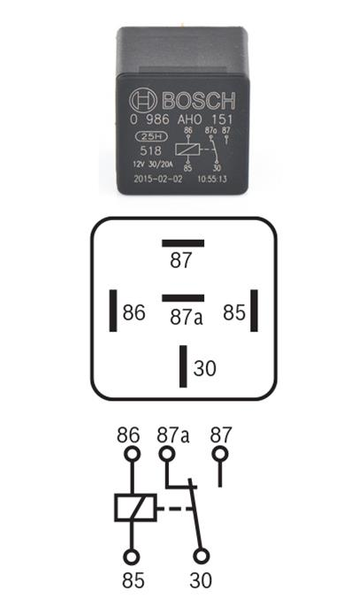 P0204 - Fuel Injector 4 Circuit / Open Theory of Operation The Powertrain Control Module (PCM) actuates the solenoid in the Fuel Injector causing the needle valve to rise and fuel flows through the spray holes in the nozzle tip into the combustion chamber. The PCM has a common internal driver circuit to all three Fuel Injectors on each bank. If any injector circuit on a given bank has a short to ground or a short to voltage, a DTC will be set for all three Fuel Injectors on that bank. Fuel Injectors 1,2,3 are grouped together on bank 1. Fuel Injectors 4,5,6 are grouped together on bank 2. The MIL will illuminate immediately after the diagnostic runs and fails twice. During this time the customer may experience engine surge or stumble. The MIL lamp will turn off once the diagnostic runs and passes in four consecutive drive cycles. When Monitored: Every 20 milliseconds when the ignition is on. Set Condition: When the Fuel Injector current falls below a calibrated threshold. Possible Causes HIGH SIDE DRIVER CIRCUIT OPEN/HIGH RESISTANCE LOW SIDE DRIVER CIRCUIT OPEN/HIGH RESISTANCE HIGH SIDE DRIVER CIRCUIT SHORTED TO GROUND LOW SIDE DRIVER CIRCUIT SHORTED TO GROUND HIGH SIDE DRIVER CIRCUIT SHORTED TO VOLTAGE LOW SIDE DRIVER CIRCUIT SHORTED TO VOLTAGE DRIVER CIRCUITS SHORTED TOGETHER VALVE COVER PASS THROUGH HARNESS FUEL INJECTOR POWERTRAIN CONTROL MODULE (PCM)– ONLY WHEN ALL INJECTOR WIRING TESTS GOOD AND ALL 3 DTCS ON THE BANK ARE ACTIVE Always perform the Pre-Diagnostic Troubleshooting procedure before proceeding. (Refer to 28 - DTC-Based Diagnostics/MODULE, Powertrain Control (PCM) - Standard Procedure). Diagnostic Test 1. ACTIVE DTC 1. Ignition on, engine not running. 2. With the scan tool check for active DTCs. Is the DTC active? Yes • Go To 2 No • Perform the INTERMITTENT CONDITION diagnostic procedure. (Refer to 28 - DTC-Based Diagnostics/MODULE, Powertrain Control (PCM) - Standard Procedure). 2. CHECK EACH FUEL INJECTOR CIRCUIT FOR AN OPEN/HIGH RESISTANCE 1. Turn the ignition off. 2. Disconnect the PCM C1 harness connector. 3. Measure the resistance between the: • (K614) Fuel Injector 4 High Side Driver circuit and the (K14) Fuel Injector 4 Low Side Driver circuit at the PCM C1 harness connector. • (K38) Fuel Injector 5 High Side Driver circuit and the (K638) Fuel Injector 5 Low Side Driver circuit at the PCM C1 harness connector. • (K658) Fuel Injector 6 High Side Driver circuit and the (K58) Fuel Injector 6 Low Side Driver circuit at the PCM C1 harness connector. NOTE: Be sure to zero out the Ohm meter prior to checking the Fuel Injector circuit. Resistance reading should be between 0-1 Ohm. Is the resistance between 0-1 Ohm for each Fuel Injector circuit? Yes • Go To 3 No • Go To 8 3. CHECK EACH FUEL INJECTOR CIRCUIT FOR A SHORT TO GROUND 1. Measure the resistance between ground and the: • (K614) Fuel Injector 4 High Side Driver circuit at the PCM C1 harness connector. • (K38) Fuel Injector 5 High Side Driver circuit at the PCM C1 harness connector. • (K658) Fuel Injector 6 High Side Driver circuit at the PCM C1 harness connector. NOTE: There should be no continuity between the circuit and ground. Is the resistance below 10k Ohms on any injector circuits? Yes • Go To 12 No • Go To 4 4. CHECKING FOR INJECTOR CONTROL CIRCUITS SHORTED TOGETHER 1. Disconnect the valve cover pass through wires at each Bank 2 Fuel Injector terminal. NOTE: Do not disconnect the valve cover pass through harness from the engine harness. 2. At the PCM C1 harness connector, measure the resistance between ALL (Bank 2) Low AND High Side Control circuits: K614(High 4), K14(Low 4), K38(High 5), K638(Low 5), K658(High 6), and K58(Low 6). Is the resistance below 10k ohms between any Injector Control circuits? Yes • Repair the Injector Control circuits that are shorted together. • Perform the POWERTRAIN VERIFICATION TEST - 6.7L. (Refer to 28 - DTC-Based Diagnostics/MODULE, Powertrain Control (PCM) - Standard Procedure). No • Go To 5 5. ISOLATE CYLINDER 4 FUEL INJECTOR 1. Reconnect the PCM C1 harness connector to the PCM. 2. Leave the valve cover pass through wires disconnected at the Cylinder 4 Fuel Injector terminals. 3. Reconnect the valve cover pass through wires at the Cylinder 5 and 6 Fuel Injector terminals. NOTE: Torque the Injector terminal nuts to 8.8 in-lbs. 4. Place electrical tape on the ends of the disconnected valve cover pass through wires to prevent the Injector terminal nuts from coming in contact with each other or the engine block. 5. Place the valve cover on the engine. NOTE: It is not necessary to bolt the valve cover in place. 6. Ignition on, engine not running. 7. With the scan tool, erase all DTCs. 8. Start the engine and let idle for 1 minute. 9. Ignition on, engine not running. 10. With the scan tool, read DTCs. Are multiple bank 2 injector circuit DTCs (P0204, P0205, P0206) active? Yes • Go To 6 No • Replace the Cylinder 4 Fuel Injector in accordance with the Service Information.(Refer to 14 - Fuel System/Fuel Inspection/INJECTOR(S) , Fuel/Removal) • Perform the POWERTRAIN VERIFICATION TEST - 6.7L. (Refer to 28 - DTC-Based Diagnostics/MODULE, Powertrain Control (PCM) - Standard Procedure). 6. ISOLATE CYLINDER 5 FUEL INJECTOR 1. Reconnect the valve cover pass through wires at the Cylinder 4 Fuel Injector terminals. NOTE: Torque the Injector terminal nuts to 8.8 in-lbs. 2. Disconnect the valve cover pass through wires at the Cylinder 5 Fuel Injector terminals. 3. Place electrical tape on the ends of the disconnected valve cover pass through wires to prevent the injector terminal nuts from coming in contact with each other or the engine block. 4. Place the valve cover on the engine. NOTE: It is not necessary to bolt the valve cover in place. 5. Ignition on, engine not running. 6. With the scan tool, erase all DTCs. 7. Start the engine and let idle for 1 minute. 8. Ignition on, engine not running. 9. With the scan tool, read DTCs. Are multiple bank 2 injector circuit DTCs (P0204, P0205, P0206) active? Yes • Go To 7 No • Replace the Cylinder 5 Fuel Injector in accordance with the Service Information.(Refer to 14 - Fuel System/Fuel Inspection/INJECTOR(S) , Fuel/Removal) • Perform the POWERTRAIN VERIFICATION TEST - 6.7L. (Refer to 28 - DTC-Based Diagnostics/MODULE, Powertrain Control (PCM) - Standard Procedure). 7. ISOLATE CYLINDER 6 FUEL INJECTOR 1. Reconnect the valve cover pass through wires at the cylinder 5 fuel injector terminals. NOTE: Torque the injector terminal nuts to 8.8 in-lbs. 2. Disconnect the valve cover pass through wires at the cylinder 6 fuel injector terminals. 3. Place electrical tape on the ends of the disconnected valve cover pass through wires to prevent the injector terminal nuts from coming in contact with each other or the engine block. 4. Place the valve cover on the engine. NOTE: It is not necessary to bolt the valve cover in place. 5. Ignition on, engine not running. 6. With the scan tool, erase all DTCs. 7. Start the engine and let idle for 1 minute. 8. Ignition on, engine not running. 9. With the scan tool, read DTCs. Are multiple bank 2 injector circuit DTCs (P0204, P0205, P0206) active? Yes • Replace the Powertrain Control Module in accordance with the Service Information. • Perform the POWERTRAIN VERIFICATION TEST - 6.7L. (Refer to 28 - DTC-Based Diagnostics/MODULE, Powertrain Control (PCM) - Standard Procedure). No • Replace the Cylinder 6 Fuel Injector in accordance with the Service Information.(Refer to 14 - Fuel System/Fuel Inspection/INJECTOR(S) , Fuel/Removal) • Perform the POWERTRAIN VERIFICATION TEST - 6.7L. (Refer to 28 - DTC-Based Diagnostics/MODULE, Powertrain Control (PCM) - Standard Procedure). 8. CHECK THE VALVE COVER PASS THROUGH HARNESS CIRCUIT NOTE: Perform the following tests on the Fuel Injector circuit which was faulty. 1. Disconnect the Valve Cover Pass Through harness connector. 2. Measure the resistance between the Low Side Driver circuit and the High Side Driver circuit at the Valve Cover Pass Through connector terminals. NOTE: Be sure to zero the Ohm meter prior to checking the Fuel Injector circuit. Is the resistance between 0-1 Ohm? Yes • Go To 9 No • Go To 11 9. CHECK THE HIGH SIDE CIRCUITS IN ENGINE HARNESS 1. Measure the resistance of the High Side Driver circuit between the Valve Cover Pass Through harness connector and the PCM C1 harness connector. NOTE: Be sure to zero the Ohm meter prior to checking the Fuel Injector circuit. Is the resistance between 0-1 Ohm? Yes • Go To 10 No • Repair the High Side Driver circuit for an open or high resistance. • Perform the POWERTRAIN VERIFICATION TEST - 6.7L. (Refer to 28 - DTC-Based Diagnostics/MODULE, Powertrain Control (PCM) - Standard Procedure). 10. CHECK THE LOW SIDE CIRCUITS IN ENGINE HARNESS 1. Measure the resistance of the Low Side Driver circuit between the Valve Cover Pass Through harness connector and the PCM C1 harness connector. NOTE: Be sure to zero the Ohm meter prior to checking the Fuel Injector circuit. Is the resistance between 0-1 Ohm? Yes • Test complete. Perform the INTERMITTENT CONDITION diagnostic procedure. (Refer to 28 - DTC- Based Diagnostics/MODULE, Powertrain Control (PCM) - Standard Procedure). No • Repair the Low Side Driver circuit for an open or high resistance. • Perform the POWERTRAIN VERIFICATION TEST - 6.7L. (Refer to 28 - DTC-Based Diagnostics/MODULE, Powertrain Control (PCM) - Standard Procedure). 11. CHECK FUEL INJECTORS 1. Disconnect all bank 2 Fuel Injector wires at the Fuel Injectors. 2. Measure the resistance across the terminals at the Fuel Injector. NOTE: Be sure to zero the Ohm meter prior to checking the Fuel Injector circuit. Is the resistance between 0-1 Ohm? Yes • Replace the Valve Cover Pass Through harness in accordance with the service information. • Perform the POWERTRAIN VERIFICATION TEST - 6.7L. (Refer to 28 - DTC-Based Diagnostics/MODULE, Powertrain Control (PCM) - Standard Procedure). No • Replace the Fuel Injector in accordance with the Service Information.(Refer to 14 - Fuel System/Fuel Inspection/INJECTOR(S) , Fuel/Removal) • Perform the POWERTRAIN VERIFICATION TEST - 6.7L. (Refer to 28 - DTC-Based Diagnostics/MODULE, Powertrain Control (PCM) - Standard Procedure). 12. CHECK FOR THE DRIVER CIRCUITS SHORTED TOGETHER 1. Disconnect all bank 2 Fuel Injector wires at the Fuel Injectors. 2. Measure the resistance between all bank 2 Driver circuits at the PCM C1 harness connector. Is the resistance below 10k Ohms between any circuits? Yes • Go To 13 No • Go To 14 13. CHECK THE VALVE COVER PASS THROUGH HARNESS CIRCUITS 1. Disconnect the Valve Cover Pass Through harness connector. 2. Measure the resistance between all bank 2 Driver circuits of the Valve Cover Pass Through connector terminals. Is the resistance below 10k Ohms between any circuits? Yes • Replace the Valve Cover Pass Through harness in accordance with the service information. • Perform the POWERTRAIN VERIFICATION TEST - 6.7L. (Refer to 28 - DTC-Based Diagnostics/MODULE, Powertrain Control (PCM) - Standard Procedure). No • Repair the short between the bank 2 Driver circuits in the engine harness. • Perform the POWERTRAIN VERIFICATION TEST - 6.7L. (Refer to 28 - DTC-Based Diagnostics/MODULE, Powertrain Control (PCM) - Standard Procedure). 14. CHECK THE HIGH SIDE DRIVER CIRCUIT FOR A SHORT TO GROUND NOTE: Perform the following tests on the Fuel Injector circuit which was faulty. 1. Disconnect the Valve Cover Pass Through harness connector . 2. Measure the resistance between ground and the High Side Driver circuit at the PCM C1 connector. Is the resistance below 10k Ohms? Yes • Repair the High Side Driver circuit for a short to ground. • Perform the POWERTRAIN VERIFICATION TEST - 6.7L. (Refer to 28 - DTC-Based Diagnostics/MODULE, Powertrain Control (PCM) - Standard Procedure). No • Go To 15 15. CHECK THE LOW SIDE DRIVER CIRCUIT FOR A SHORT TO GROUND 1. Measure the resistance between ground and the Low Side Driver circuit at the PCM C1 connector. Is the resistance below 10k Ohms? Yes • Repair the Low Side Driver circuit for a short to ground. • Perform the POWERTRAIN VERIFICATION TEST - 6.7L. (Refer to 28 - DTC-Based Diagnostics/MODULE, Powertrain Control (PCM) - Standard Procedure). No • Go To 16 16. CHECK THE FUEL INJECTORS 1. Measure the resistance between ground and one of the Fuel Injector terminals. Is the resistance below 10k Ohms? Yes • Replace the Fuel Injector in accordance with the Service Information.(Refer to 14 - Fuel System/Fuel Inspection/INJECTOR(S) , Fuel/Removal) • Perform the POWERTRAIN VERIFICATION TEST - 6.7L. (Refer to 28 - DTC-Based Diagnostics/MODULE, Powertrain Control (PCM) - Standard Procedure). No • Replace the Valve Cover Pass Through harness in accordance with the service information. • Perform the POWERTRAIN VERIFICATION TEST - 6.7L. (Refer to 28 - DTC-Based Diagnostics/MODULE, Powertrain Control (PCM) - Standard Procedure).P0203 - Fuel Injector 3 Circuit / Open Theory of Operation The Powertrain Control Module (PCM) actuates the solenoid in the Fuel Injector causing the needle valve to rise and fuel flows through the spray holes in the nozzle tip into the combustion chamber. The PCM has a common internal driver circuit to all three Fuel Injectors on each bank. If any injector circuit on a given bank has a short to ground or a short to voltage, a DTC will be set for all three Fuel Injectors on that bank. Fuel Injectors 1,2,3 are grouped together on bank 1. Fuel Injectors 4,5,6 are grouped together on bank 2. The MIL will illuminate immediately after the diagnostic runs and fails twice. During this time the customer may experience engine surge or stumble. The MIL lamp will turn off once the diagnostic runs and passes in four consecutive drive cycles. When Monitored: Every 20 milliseconds when the ignition is on. Set Condition: When the Fuel Injector current falls below a calibrated threshold. Possible Causes HIGH SIDE DRIVER CIRCUIT OPEN/HIGH RESISTANCE LOW SIDE DRIVER CIRCUIT OPEN/HIGH RESISTANCE HIGH SIDE DRIVER CIRCUIT SHORTED TO GROUND LOW SIDE DRIVER CIRCUIT SHORTED TO GROUND HIGH SIDE DRIVER CIRCUIT SHORTED TO VOLTAGE LOW SIDE DRIVER CIRCUIT SHORTED TO VOLTAGE DRIVER CIRCUITS SHORTED TOGETHER VALVE COVER PASS THROUGH HARNESS FUEL INJECTOR POWERTRAIN CONTROL MODULE (PCM)– ONLY WHEN ALL INJECTOR WIRING TESTS GOOD AND ALL 3 DTCS ON THE BANK ARE ACTIVE Always perform the Pre-Diagnostic Troubleshooting procedure before proceeding. (Refer to 28 - DTC-Based Diagnostics/MODULE, Powertrain Control (PCM) - Standard Procedure). Diagnostic Test 1. ACTIVE DTC 1. Ignition on, engine not running. 2. With the scan tool check for active DTCs. Is the DTC active? Yes • Go To 2 No • Perform the INTERMITTENT CONDITION diagnostic procedure. (Refer to 28 - DTC-Based Diagnostics/MODULE, Powertrain Control (PCM) - Standard Procedure). 2. CHECK EACH FUEL INJECTOR CIRCUIT FOR AN OPEN/HIGH RESISTANCE 1. Turn the ignition off. 2. Disconnect the PCM C1 harness connector. 3. Measure the resistance between the: • (K11) Fuel Injector 1 High Side Driver circuit and the (K611) Fuel Injector 1 Low Side Driver circuit at the PCM C1 harness connector. • (K12) Fuel Injector 2 High Side Driver circuit and the (K612) Fuel Injector 2 Low Side Driver circuit at the PCM C1 harness connector. • (K13) Fuel Injector 3 High Side Driver circuit and the (K613) Fuel Injector 3 Low Side Driver circuit at the PCM C1 harness connector. NOTE: Be sure to zero out the Ohm meter prior to checking the Fuel Injector circuit. Resistance reading should be between 0-1 Ohm. Is the resistance between 0-1 Ohm for each Fuel Injector circuit? Yes • Go To 3 No • Go To 8 3. CHECK EACH FUEL INJECTOR CIRCUIT FOR A SHORT TO GROUND 1. Measure the resistance between ground and the: • (K11) Fuel Injector 1 High Side Driver circuit at the PCM C1 harness connector. • (K12) Fuel Injector 2 High Side Driver circuit at the PCM C1 harness connector. (K13) Fuel Injector 3 High Side Driver circuit at the PCM C1 harness connector. NOTE: There should be no continuity between the circuit and ground. Is the resistance below 10k Ohms on any injector circuits? Yes • Go To 12 No • Go To 4 4. CHECKING FOR INJECTOR CONTROL CIRCUITS SHORTED TOGETHER 1. Disconnect the valve cover pass through wires at each Bank 1 Fuel Injector terminal. NOTE: Do not disconnect the valve cover pass through harness from the engine harness. 2. At the PCM C1 harness connector, measure the resistance between ALL (Bank 1) Low AND High Side Control circuits: K11(High 1), K611(Low 1), K12(High 2), K612(Low 2), K13(High 3), and K613(Low 3). Is the resistance below 10k ohms between any Injector Control circuits? Yes • Repair the Injector Control circuits that are shorted together. • Perform the POWERTRAIN VERIFICATION TEST - 6.7L. (Refer to 28 - DTC-Based Diagnostics/MODULE, Powertrain Control (PCM) - Standard Procedure). No • Go To 5 5. ISOLATE CYLINDER 1 FUEL INJECTOR 1. Reconnect the PCM C1 harness connector to the PCM. 2. Leave the valve cover pass through wires disconnected at the Cylinder 1 Fuel Injector terminals. 3. Reconnect the valve cover pass through wires at the Cylinder 2 and 3 Fuel Injector terminals. NOTE: Torque the Injector terminal nuts to 8.8 in-lbs. 4. Place electrical tape on the ends of the disconnected valve cover pass through wires to prevent the Injector terminal nuts from coming in contact with each other or the engine block. 5. Place the valve cover on the engine. NOTE: It is not necessary to bolt the valve cover in place. 6. Ignition on, engine not running. 7. With the scan tool, erase all DTCs. 8. Start the engine and let idle for 1 minute. 9. Ignition on, engine not running. 10. With the scan tool, read DTCs. Are multiple bank 1 injector circuit DTCs (P0201, P0202, P0203) active? Yes • Go To 6 No • Replace the Cylinder 1 Fuel Injector in accordance with the Service Information.(Refer to 14 - Fuel System/Fuel Inspection/INJECTOR(S) , Fuel/Removal) • Perform the POWERTRAIN VERIFICATION TEST - 6.7L. (Refer to 28 - DTC-Based Diagnostics/MODULE, Powertrain Control (PCM) - Standard Procedure). 6. ISOLATE CYLINDER 2 FUEL INJECTOR 1. Reconnect the valve cover pass through wires at the Cylinder 1 Fuel Injector terminals. NOTE: Torque the Injector terminal nuts to 8.8 in-lbs. 2. Disconnect the valve cover pass through wires at the Cylinder 2 Fuel Injector terminals. 3. Place electrical tape on the ends of the disconnected valve cover pass through wires to prevent the injector terminal nuts from coming in contact with each other or the engine block. 4. Place the valve cover on the engine. NOTE: It is not necessary to bolt the valve cover in place. 5. Ignition on, engine not running. 6. With the scan tool, erase all DTCs. 7. Start the engine and let idle for 1 minute. 8. Ignition on, engine not running. 9. With the scan tool, read DTCs. Are multiple bank 1 injector circuit DTCs (P0201, P0202, P0203) active? Yes • Go To 7 No • Replace the Cylinder 2 Fuel Injector in accordance with the Service Information.(Refer to 14 - FuelSystem/Fuel Inspection/INJECTOR(S) , Fuel/Removal) • Perform the POWERTRAIN VERIFICATION TEST - 6.7L. (Refer to 28 - DTC-Based Diagnostics/MODULE, Powertrain Control (PCM) - Standard Procedure). 7. ISOLATE CYLINDER 3 FUEL INJECTOR 1. Reconnect the valve cover pass through wires at the cylinder 2 fuel injector terminals. NOTE: Torque the injector terminal nuts to 8.8 in-lbs. 2. Disconnect the valve cover pass through wires at the cylinder 3 fuel injector terminals. 3. Place electrical tape on the ends of the disconnected valve cover pass through wires to prevent the injector terminal nuts from coming in contact with each other or the engine block. 4. Place the valve cover on the engine. NOTE: It is not necessary to bolt the valve cover in place. 5. Ignition on, engine not running. 6. With the scan tool, erase all DTCs. 7. Start the engine and let idle for 1 minute. 8. Ignition on, engine not running. 9. With the scan tool, read DTCs. Are multiple bank 1 injector circuit DTCs (P0201, P0202, P0203) active? Yes • Replace the Powertrain Control Module in accordance with the service information. • Perform the POWERTRAIN VERIFICATION TEST - 6.7L. (Refer to 28 - DTC-Based Diagnostics/MODULE, Powertrain Control (PCM) - Standard Procedure). No • Replace the Cylinder 3 Fuel Injector in accordance with the Service Information.(Refer to 14 - Fuel System/Fuel Inspection/INJECTOR(S) , Fuel/Removal) • Perform the POWERTRAIN VERIFICATION TEST - 6.7L. (Refer to 28 - DTC-Based Diagnostics/MODULE, Powertrain Control (PCM) - Standard Procedure). 8. CHECK THE VALVE COVER PASS THROUGH HARNESS CIRCUIT NOTE: Perform the following tests on the Fuel Injector circuit which was faulty. 1. Disconnect the Valve Cover Pass Through harness connector. 2. Measure the resistance between the Low Side Driver circuit and the High Side Driver circuit at the Valve Cover Pass Through connector terminals. NOTE: Be sure to zero the Ohm meter prior to checking the Fuel Injector circuit. Is the resistance between 0-1 Ohm? Yes • Go To 9 No • Go To 11 9. CHECK THE HIGH SIDE CIRCUIT IN ENGINE HARNESS 1. Measure the resistance of the High Side Driver circuit between the Valve Cover Pass Through harness connector and the PCM C1 harness connector. NOTE: Be sure to zero the Ohm meter prior to checking the Fuel Injector circuit. Is the resistance between 0-1 Ohm? Yes • Go To 10 No • Repair the High Side Driver circuit for an open or high resistance. • Perform the POWERTRAIN VERIFICATION TEST - 6.7L. (Refer to 28 - DTC-Based Diagnostics/MODULE, Powertrain Control (PCM) - Standard Procedure). 10. CHECK THE LOW SIDE CIRCUIT IN ENGINE HARNESS 1.Measure the resistance of the Low Side Driver circuit between the Valve Cover Pass Through harness connector and the PCM C1 harness connector. NOTE: Be sure to zero the Ohm meter prior to checking the Fuel Injector circuit. Is the resistance between 0-1 Ohm? Yes • Test complete. Perform the INTERMITTENT CONDITION diagnostic procedure. (Refer to 28 - DTC- Based Diagnostics/MODULE, Powertrain Control (PCM) - Standard Procedure). No • Repair the Low Side Driver circuit for an open or high resistance. • Perform the POWERTRAIN VERIFICATION TEST - 6.7L. (Refer to 28 - DTC-Based Diagnostics/MODULE, Powertrain Control (PCM) - Standard Procedure). 11. CHECK THE FUEL INJECTORS 1. Disconnect all bank 1 Fuel Injector wires at the Fuel Injectors. 2. Measure the resistance across the terminals at the Fuel Injector. NOTE: Be sure to zero the Ohm meter prior to checking the Fuel Injector circuit. Is the resistance between 0-1 Ohm? Yes • Replace the Valve Cover Pass Through harness. • Perform the POWERTRAIN VERIFICATION TEST - 6.7L. (Refer to 28 - DTC-Based Diagnostics/MODULE, Powertrain Control (PCM) - Standard Procedure). No • Replace the Fuel Injector in accordance with the Service Information.(Refer to 14 - Fuel System/Fuel Inspection/INJECTOR(S) , Fuel/Removal) • Perform the POWERTRAIN VERIFICATION TEST - 6.7L. (Refer to 28 - DTC-Based Diagnostics/MODULE, Powertrain Control (PCM) - Standard Procedure). 12. CHECK FOR THE DRIVER CIRCUITS SHORTED TOGETHER 1. Disconnect all bank 1 Fuel Injector wires at the Fuel Injectors. 2. Measure the resistance between all bank 1 Driver circuits at the PCM C1 harness connector. Is the resistance below 10k Ohms between any circuits? Yes • Go To 13 No • Go To 14 13. CHECK THE VALVE COVER PASS THROUGH HARNESS CIRCUIT 1. Disconnect the Valve Cover Pass Through harness connector. 2. Measure the resistance between all bank 1 Driver circuits of the Valve Cover Pass Through connector terminals. Is the resistance below 10k Ohms between any circuits? Yes • Replace the Valve Cover Pass Through harness in accordance with the service information. • Perform the POWERTRAIN VERIFICATION TEST - 6.7L. (Refer to 28 - DTC-Based Diagnostics/MODULE, Powertrain Control (PCM) - Standard Procedure). No • Repair the short between the bank 1 Driver circuits in the engine harness. • Perform the POWERTRAIN VERIFICATION TEST - 6.7L. (Refer to 28 - DTC-Based Diagnostics/MODULE, Powertrain Control (PCM) - Standard Procedure). 14. CHECK THE HIGH SIDE DRIVER CIRCUIT FOR A SHORT TO GROUND NOTE: Perform the following tests on the Fuel Injector circuit which was faulty. 1. Disconnect the Valve Cover Pass Through harness connector. 2. Measure the resistance between ground and the High Side Driver circuit at the PCM C1 harness connector. Is the resistance below 10k Ohms? Yes • Repair the High Side Driver circuit for a short to ground. • Perform the POWERTRAIN VERIFICATION TEST - 6.7L. (Refer to 28 - DTC-Based Diagnostics/MODULE, Powertrain Control (PCM) - Standard Procedure). No • Go To 15 15. CHECK THE LOW SIDE DRIVER CIRCUIT FOR A SHORT TO GROUND 1. Measure the resistance between ground and the Low Side Driver circuit at the PCM C1 harness connector. Is the resistance below 10k Ohms? Yes • Repair the Low Side Driver circuit for a short to ground. • Perform the POWERTRAIN VERIFICATION TEST - 6.7L. (Refer to 28 - DTC-Based Diagnostics/MODULE, Powertrain Control (PCM) - Standard Procedure). No • Go To 16 16. CHECK THE FUEL INJECTORS 1. Measure the resistance between ground and one of the Fuel Injector terminals. Is the resistance below 10k Ohms? Yes • Replace the Fuel Injector in accordance with the service information. • Perform the POWERTRAIN VERIFICATION TEST - 6.7L. (Refer to 28 - DTC-Based Diagnostics/MODULE, Powertrain Control (PCM) - Standard Procedure). No • Replace the Valve Cover Pass Through harness in accordance with the service information. • Perform the POWERTRAIN VERIFICATION TEST - 6.7L. (Refer to 28 - DTC-Based Diagnostics/MODULE, Powertrain Control (PCM) - Standard Procedure).P0202 - Fuel Injector 2 Circuit / Open Theory of Operation The Powertrain Control Module (PCM) actuates the solenoid in the Fuel Injector causing the needle valve to rise and fuel flows through the spray holes in the nozzle tip into the combustion chamber. The PCM has a common internal driver circuit to all three Fuel Injectors on each bank. If any injector circuit on a given bank has a short to ground or a short to voltage, a DTC will be set for all three Fuel Injectors on that bank. Fuel Injectors 1,2,3 are grouped together on bank 1. Fuel Injectors 4,5,6 are grouped together on bank 2. The MIL will illuminate immediately after the diagnostic runs and fails twice. During this time the customer may experience engine surge or stumble. The MIL lamp will turn off once the diagnostic runs and passes in four consecutive drive cycles. When Monitored: Every 20 milliseconds when the ignition is on. Set Condition: When the Fuel Injector current falls below a calibrated threshold. Possible Causes HIGH SIDE DRIVER CIRCUIT OPEN/HIGH RESISTANCE LOW SIDE DRIVER CIRCUIT OPEN/HIGH RESISTANCE HIGH SIDE DRIVER CIRCUIT SHORTED TO GROUND LOW SIDE DRIVER CIRCUIT SHORTED TO GROUND HIGH SIDE DRIVER CIRCUIT SHORTED TO VOLTAGE LOW SIDE DRIVER CIRCUIT SHORTED TO VOLTAGE DRIVER CIRCUITS SHORTED TOGETHER VALVE COVER PASS THROUGH HARNESS FUEL INJECTOR POWERTRAIN CONTROL MODULE (PCM)– ONLY WHEN ALL INJECTOR WIRING TESTS GOOD AND ALL 3 DTCS ON THE BANK ARE ACTIVE Always perform the Pre-Diagnostic Troubleshooting procedure before proceeding. (Refer to 28 - DTC-Based Diagnostics/MODULE, Powertrain Control (PCM) - Standard Procedure). Diagnostic Test 1. ACTIVE DTC 1. Ignition on, engine not running. With the scan tool check for active DTCs. Is the DTC active? Yes • Go To 2 No • Perform the INTERMITTENT CONDITION diagnostic procedure. (Refer to 28 - DTC-Based Diagnostics/MODULE, Powertrain Control (PCM) - Standard Procedure). 2. CHECK EACH FUEL INJECTOR CIRCUIT FOR AN OPEN/HIGH RESISTANCE 1. Turn the ignition off. 2. Disconnect the PCM C1 harness connector. 3. Measure the resistance between the: • (K11) Fuel Injector 1 High Side Driver circuit and the (K611) Fuel Injector 1 Low Side Driver circuit at the PCM C1 harness connector. • (K12) Fuel Injector 2 High Side Driver circuit and the (K612) Fuel Injector 2 Low Side Driver circuit at the PCM C1 harness connector. • (K13) Fuel Injector 3 High Side Driver circuit and the (K613) Fuel Injector 3 Low Side Driver circuit at the PCM C1 harness connector. NOTE: Be sure to zero out the Ohm meter prior to checking the Fuel Injector circuit. Resistance reading should be between 0-1 Ohm. Is the resistance between 0-1 Ohm for each Fuel Injector circuit? Yes • Go To 3 No • Go To 8 3. CHECK EACH FUEL INJECTOR CIRCUIT FOR A SHORT TO GROUND 1. Measure the resistance between ground and the: • (K11) Fuel Injector 1 High Side Driver circuit at the PCM C1 harness connector. • (K12) Fuel Injector 2 High Side Driver circuit at the PCM C1 harness connector. (K13) Fuel Injector 3 High Side Driver circuit at the PCM C1 harness connector. NOTE: There should be no continuity between the circuit and ground. Is the resistance below 10k Ohms on any injector circuits? Yes • Go To 12 No • Go To 4 4. CHECKING FOR INJECTOR CONTROL CIRCUITS SHORTED TOGETHER 1. Disconnect the valve cover pass through wires at each Bank 1 Fuel Injector terminal. NOTE: Do not disconnect the valve cover pass through harness from the engine harness. 2. At the PCM C1 harness connector, measure the resistance between ALL (Bank 1) Low AND High Side Control circuits: K11(High 1), K611(Low 1), K12(High 2), K612(Low 2), K13(High 3), and K613(Low 3). Is the resistance below 10k ohms between any Injector Control circuits? Yes • Repair the Injector Control circuits that are shorted together. • Perform the POWERTRAIN VERIFICATION TEST - 6.7L. (Refer to 28 - DTC-Based Diagnostics/MODULE, Powertrain Control (PCM) - Standard Procedure). No • Go To 5 5. ISOLATE CYLINDER 1 FUEL INJECTOR 1. Reconnect the PCM C1 harness connector to the PCM. 2. Leave the valve cover pass through wires disconnected at the Cylinder 1 Fuel Injector terminals. 3. Reconnect the valve cover pass through wires at the Cylinder 2 and 3 Fuel Injector terminals. NOTE: Torque the Injector terminal nuts to 8.8 in-lbs. 4. Place electrical tape on the ends of the disconnected valve cover pass through wires to prevent the Injector terminal nuts from coming in contact with each other or the engine block. 5. Place the valve cover on the engine. NOTE: It is not necessary to bolt the valve cover in place. 6. Ignition on, engine not running. 7. With the scan tool, erase all DTCs. 8. Start the engine and let idle for 1 minute. 9. Ignition on, engine not running. 10. With the scan tool, read DTCs. Are multiple bank 1 injector circuit DTCs (P0201, P0202, P0203) active? Yes • Go To 6 No • Replace the Cylinder 1 Fuel Injector in accordance with the Service Information.(Refer to 14 - Fuel System/Fuel Inspection/INJECTOR(S) , Fuel/Removal) • Perform the POWERTRAIN VERIFICATION TEST - 6.7L. (Refer to 28 - DTC-Based Diagnostics/MODULE, Powertrain Control (PCM) - Standard Procedure). 6. ISOLATE CYLINDER 2 FUEL INJECTOR 1. Reconnect the valve cover pass through wires at the Cylinder 1 Fuel Injector terminals. NOTE: Torque the Injector terminal nuts to 8.8 in-lbs. 2. Disconnect the valve cover pass through wires at the Cylinder 2 Fuel Injector terminals. 3. Place electrical tape on the ends of the disconnected valve cover pass through wires to prevent the injector terminal nuts from coming in contact with each other or the engine block. 4. Place the valve cover on the engine. NOTE: It is not necessary to bolt the valve cover in place. 5. Ignition on, engine not running. 6. With the scan tool, erase all DTCs. 7. Start the engine and let idle for 1 minute. 8. Ignition on, engine not running. 9. With the scan tool, read DTCs. Are multiple bank 1 injector circuit DTCs (P0201, P0202, P0203) active? Yes • Go To 7 No • Replace the Cylinder 2 Fuel Injector in accordance with the Service Information.(Refer to 14 - Fuel System/Fuel Inspection/INJECTOR(S) , Fuel/Removal) • Perform the POWERTRAIN VERIFICATION TEST - 6.7L. (Refer to 28 - DTC-Based Diagnostics/MODULE, Powertrain Control (PCM) - Standard Procedure). 7. ISOLATE CYLINDER 3 FUEL INJECTOR 1. Reconnect the valve cover pass through wires at the cylinder 2 fuel injector terminals. NOTE: Torque the injector terminal nuts to 8.8 in-lbs. 2. Disconnect the valve cover pass through wires at the cylinder 3 fuel injector terminals. 3. Place electrical tape on the ends of the disconnected valve cover pass through wires to prevent the injector terminal nuts from coming in contact with each other or the engine block. 4. Place the valve cover on the engine. NOTE: It is not necessary to bolt the valve cover in place. 5. Ignition on, engine not running. 6. With the scan tool, erase all DTCs. 7. Start the engine and let idle for 1 minute. 8. Ignition on, engine not running. 9. With the scan tool, read DTCs. Are multiple bank 1 injector circuit DTCs (P0201, P0202, P0203) active? Yes • Replace the Powertrain Control Module in accordance with the service information. • Perform the POWERTRAIN VERIFICATION TEST - 6.7L. (Refer to 28 - DTC-Based Diagnostics/MODULE, Powertrain Control (PCM) - Standard Procedure). No • Replace the Cylinder 3 Fuel Injector in accordance with the Service Information.(Refer to 14 - Fuel System/Fuel Inspection/INJECTOR(S) , Fuel/Removal) • Perform the POWERTRAIN VERIFICATION TEST - 6.7L. (Refer to 28 - DTC-Based Diagnostics/MODULE, Powertrain Control (PCM) - Standard Procedure). 8. CHECK THE VALVE COVER PASS THROUGH HARNESS CIRCUIT NOTE: Perform the following tests on the Fuel Injector circuit which was faulty. 1. Disconnect the Valve Cover Pass Through harness connector. 2. Measure the resistance between the Low Side Driver circuit and the High Side Driver circuit at the Valve Cover Pass Through connector terminals. NOTE: Be sure to zero the Ohm meter prior to checking the Fuel Injector circuit. Is the resistance between 0-1 Ohm? Yes • Go To 9 No • Go To 11 9. CHECK THE HIGH SIDE CIRCUIT IN ENGINE HARNESS 1. Measure the resistance of the High Side Driver circuit between the Valve Cover Pass Through harness connector and the PCM C1 harness connector. NOTE: Be sure to zero the Ohm meter prior to checking the Fuel Injector circuit. Is the resistance between 0-1 Ohm? Yes • Go To 10 No • Repair the High Side Driver circuit for an open or high resistance. • Perform the POWERTRAIN VERIFICATION TEST - 6.7L. (Refer to 28 - DTC-Based Diagnostics/MODULE, Powertrain Control (PCM) - Standard Procedure). 10. CHECK THE LOW SIDE CIRCUIT IN ENGINE HARNESS 1.Measure the resistance of the Low Side Driver circuit between the Valve Cover Pass Through harness connector and the PCM C1 harness connector. NOTE: Be sure to zero the Ohm meter prior to checking the Fuel Injector circuit. Is the resistance between 0-1 Ohm? Yes • Test complete. Perform the INTERMITTENT CONDITION diagnostic procedure. (Refer to 28 - DTC-Based Diagnostics/MODULE, Powertrain Control (PCM) - Standard Procedure). No • Repair the Low Side Driver circuit for an open or high resistance. • Perform the POWERTRAIN VERIFICATION TEST - 6.7L. (Refer to 28 - DTC-Based Diagnostics/MODULE, Powertrain Control (PCM) - Standard Procedure). 11. CHECK THE FUEL INJECTORS 1. Disconnect all bank 1 Fuel Injector wires at the Fuel Injectors. 2. Measure the resistance across the terminals at the Fuel Injector. NOTE: Be sure to zero the Ohm meter prior to checking the Fuel Injector circuit. Is the resistance between 0-1 Ohm? Yes • Replace the Valve Cover Pass Through harness. • Perform the POWERTRAIN VERIFICATION TEST - 6.7L. (Refer to 28 - DTC-Based Diagnostics/MODULE, Powertrain Control (PCM) - Standard Procedure). No • Replace the Fuel Injector in accordance with the Service Information.(Refer to 14 - Fuel System/Fuel Inspection/INJECTOR(S) , Fuel/Removal) • Perform the POWERTRAIN VERIFICATION TEST - 6.7L. (Refer to 28 - DTC-Based Diagnostics/MODULE, Powertrain Control (PCM) - Standard Procedure). 12. CHECK FOR THE DRIVER CIRCUITS SHORTED TOGETHER 1. Disconnect all bank 1 Fuel Injector wires at the Fuel Injectors. 2. Measure the resistance between all bank 1 Driver circuits at the PCM C1 harness connector. Is the resistance below 10k Ohms between any circuits? Yes • Go To 13 No • Go To 14 13. CHECK THE VALVE COVER PASS THROUGH HARNESS CIRCUIT 1. Disconnect the Valve Cover Pass Through harness connector. 2. Measure the resistance between all bank 1 Driver circuits of the Valve Cover Pass Through connector terminals. Is the resistance below 10k Ohms between any circuits? Yes • Replace the Valve Cover Pass Through harness in accordance with the service information. • Perform the POWERTRAIN VERIFICATION TEST - 6.7L. (Refer to 28 - DTC-Based Diagnostics/MODULE, Powertrain Control (PCM) - Standard Procedure). No • Repair the short between the bank 1 Driver circuits in the engine harness. • Perform the POWERTRAIN VERIFICATION TEST - 6.7L. (Refer to 28 - DTC-Based Diagnostics/MODULE, Powertrain Control (PCM) - Standard Procedure). 14. CHECK THE HIGH SIDE DRIVER CIRCUIT FOR A SHORT TO GROUND NOTE: Perform the following tests on the Fuel Injector circuit which was faulty. 1. Disconnect the Valve Cover Pass Through harness connector. 2. Measure the resistance between ground and the High Side Driver circuit at the PCM C1 harness connector. Is the resistance below 10k Ohms? Yes • Repair the High Side Driver circuit for a short to ground. • Perform the POWERTRAIN VERIFICATION TEST - 6.7L. (Refer to 28 - DTC-Based Diagnostics/MODULE, Powertrain Control (PCM) - Standard Procedure). No • Go To 15 15. CHECK THE LOW SIDE DRIVER CIRCUIT FOR A SHORT TO GROUND 1. Measure the resistance between ground and the Low Side Driver circuit at the PCM C1 harness connector. Is the resistance below 10k Ohms? Yes • Repair the Low Side Driver circuit for a short to ground. • Perform the POWERTRAIN VERIFICATION TEST - 6.7L. (Refer to 28 - DTC-BasedDiagnostics/MODULE, Powertrain Control (PCM) - Standard Procedure). No • Go To 16 16. CHECK THE FUEL INJECTORS 1. Measure the resistance between ground and one of the Fuel Injector terminals. Is the resistance below 10k Ohms? Yes • Replace the Fuel Injector in accordance with the service information. • Perform the POWERTRAIN VERIFICATION TEST - 6.7L. (Refer to 28 - DTC-Based Diagnostics/MODULE, Powertrain Control (PCM) - Standard Procedure). No • Replace the Valve Cover Pass Through harness in accordance with the service information. • Perform the POWERTRAIN VERIFICATION TEST - 6.7L. (Refer to 28 - DTC-Based Diagnostics/MODULE, Powertrain Control (PCM) - Standard Procedure).Now I'm asking for it to stop so I can catch up. Still got a transmission to do in the bitter cold up here. Starting at a low of +11*F (-11.6*C). Then I've gotta pack up and head to Lucile, ID to install a thermostat in a RV so the owner can stay warm with the propane furnace. Then come back here install a water pump in a !998 Dodge V10 pickup then try to muster up the strength to finish the transmission job outside in my wood shed. (Ugh!) Top it all off my winch on my ATV is shot and froze up. I need to either replace or take mine apart and see if I can repair this one. Be nice ot get the customer truck out of my shop so I can work inside out of the cold. It's so cold I watch my heater / propane bottle freeze up. Yup heater slowed way down on heat production and the propane bottle looked like a round block of dry Ice. It was freezing any moisture in the air. I even got smart last night and moved both trucks close to a building and plugged in block heaters for both. Yea I know I typically don't do that but with the hard start on Beast which I still need to do the injector o-rings. Then on Thor the warm up time with grid heaters are fairly rough and also just takes FOREVER without Mopar1973Man High Idle 3 CYL warm up which Beast has. Beast still can warm up much, much, faster than Thor. Even using exhaust brake on Thor still slow and takes forever.P0201 - Fuel Injector 1 Circuit / Open Theory of Operation The Powertrain Control Module (PCM) actuates the solenoid in the Fuel Injector causing the needle valve to rise and fuel flows through the spray holes in the nozzle tip into the combustion chamber. The PCM has a common internal driver circuit to all three Fuel Injectors on each bank. If any injector circuit on a given bank has a short to ground or a short to voltage, a DTC will be set for all three Fuel Injectors on that bank. Fuel Injectors 1,2,3 are grouped together on bank 1. Fuel Injectors 4,5,6 are grouped together on bank 2. The MIL will illuminate immediately after the diagnostic runs and fails twice. During this time the customer may experience engine surge or stumble. The MIL lamp will turn off once the diagnostic runs and passes in four consecutive drive cycles. When Monitored: Every 20 milliseconds when the ignition is on. Set Condition: When the Fuel Injector current falls below a calibrated threshold. Possible Causes HIGH SIDE DRIVER CIRCUIT OPEN/HIGH RESISTANCE LOW SIDE DRIVER CIRCUIT OPEN/HIGH RESISTANCE HIGH SIDE DRIVER CIRCUIT SHORTED TO GROUND LOW SIDE DRIVER CIRCUIT SHORTED TO GROUND HIGH SIDE DRIVER CIRCUIT SHORTED TO VOLTAGE LOW SIDE DRIVER CIRCUIT SHORTED TO VOLTAGE DRIVER CIRCUITS SHORTED TOGETHER VALVE COVER PASS THROUGH HARNESS FUEL INJECTOR POWERTRAIN CONTROL MODULE (PCM)– ONLY WHEN ALL INJECTOR WIRING TESTS GOOD AND ALL 3 DTCS ON THE BANK ARE ACTIVE Always perform the Pre-Diagnostic Troubleshooting procedure before proceeding. (Refer to 28 - DTC- Based Diagnostics/MODULE, Powertrain Control (PCM) - Standard Procedure). Diagnostic Test 1. ACTIVE DTC 1. Ignition on, engine not running. 2. With the scan tool check for active DTCs. Is the DTC active? Yes • Go To 2 No • Perform the INTERMITTENT CONDITION diagnostic procedure. (Refer to 28 - DTC-Based Diagnostics/MODULE, Powertrain Control (PCM) - Standard Procedure). 2. CHECK EACH FUEL INJECTOR CIRCUIT FOR AN OPEN/HIGH RESISTANCE 1. Turn the ignition off. 2. Disconnect the PCM C1 harness connector. 3. Measure the resistance between the: • (K11) Fuel Injector 1 High Side Driver circuit and the (K611) Fuel Injector 1 Low Side Driver circuit at the PCM C1 harness connector. • (K12) Fuel Injector 2 High Side Driver circuit and the (K612) Fuel Injector 2 Low Side Driver circuit at the PCM C1 harness connector. • (K13) Fuel Injector 3 High Side Driver circuit and the (K613) Fuel Injector 3 Low Side Driver circuit at the PCM C1 harness connector. NOTE: Be sure to zero out the Ohm meter prior to checking the Fuel Injector circuit. Resistance reading should be between 0-1 Ohm. Is the resistance between 0-1 Ohm for each Fuel Injector circuit? Yes • Go To 3 No • Go To 8 3. CHECK EACH FUEL INJECTOR CIRCUIT FOR A SHORT TO GROUND 1. Measure the resistance between ground and the: (K11) Fuel Injector 1 High Side Driver circuit at the PCM C1 harness connector. (K12) Fuel Injector 2 High Side Driver circuit at the PCM C1 harness connector. (K13) Fuel Injector 3 High Side Driver circuit at the PCM C1 harness connector. NOTE: There should be no continuity between the circuit and ground. Is the resistance below 10k Ohms on any injector circuits? Yes • Go To 12 No • Go To 4 4. CHECKING FOR INJECTOR CONTROL CIRCUITS SHORTED TOGETHER 1. Disconnect the valve cover pass through wires at each Bank 1 Fuel Injector terminal. NOTE: Do not disconnect the valve cover pass through harness from the engine harness. 2. At the PCM C1 harness connector, measure the resistance between ALL (Bank 1) Low AND High Side Control circuits: K11(High 1), K611(Low 1), K12(High 2), K612(Low 2), K13(High 3), and K613(Low 3). Is the resistance below 10k ohms between any Injector Control circuits? Yes • Repair the Injector Control circuits that are shorted together. • Perform the POWERTRAIN VERIFICATION TEST - 6.7L. (Refer to 28 - DTC-Based Diagnostics/MODULE, Powertrain Control (PCM) - Standard Procedure). No • Go To 5 5. ISOLATE CYLINDER 1 FUEL INJECTOR 1. Reconnect the PCM C1 harness connector to the PCM. 2. Leave the valve cover pass through wires disconnected at the Cylinder 1 Fuel Injector terminals. 3. Reconnect the valve cover pass through wires at the Cylinder 2 and 3 Fuel Injector terminals. NOTE: Torque the Injector terminal nuts to 8.8 in-lbs. 4. Place electrical tape on the ends of the disconnected valve cover pass through wires to prevent the Injector terminal nuts from coming in contact with each other or the engine block. 5. Place the valve cover on the engine. NOTE: It is not necessary to bolt the valve cover in place. 6. Ignition on, engine not running. 7. With the scan tool, erase all DTCs. 8. Start the engine and let idle for 1 minute. 9. Ignition on, engine not running. 10. With the scan tool, read DTCs. Are multiple bank 1 injector circuit DTCs (P0201, P0202, P0203) active? Yes • Go To 6 No • Replace the Cylinder 1 Fuel Injector in accordance with the Service Information.(Refer to 14 - Fuel System/Fuel Inspection/INJECTOR(S) , Fuel/Removal) • Perform the POWERTRAIN VERIFICATION TEST - 6.7L. (Refer to 28 - DTC-Based Diagnostics/MODULE, Powertrain Control (PCM) - Standard Procedure). 6. ISOLATE CYLINDER 2 FUEL INJECTOR 1. Reconnect the valve cover pass through wires at the Cylinder 1 Fuel Injector terminals. NOTE: Torque the Injector terminal nuts to 8.8 in-lbs. 2. Disconnect the valve cover pass through wires at the Cylinder 2 Fuel Injector terminals. 3. Place electrical tape on the ends of the disconnected valve cover pass through wires to prevent the injector terminal nuts from coming in contact with each other or the engine block. 4. Place the valve cover on the engine. NOTE: It is not necessary to bolt the valve cover in place. 5. Ignition on, engine not running. 6. With the scan tool, erase all DTCs. 7. Start the engine and let idle for 1 minute. 8. Ignition on, engine not running. 9. With the scan tool, read DTCs. Are multiple bank 1 injector circuit DTCs (P0201, P0202, P0203) active? Yes • Go To 7 No • Replace the Cylinder 2 Fuel Injector in accordance with the Service Information.(Refer to 14 - Fuel System/Fuel Inspection/INJECTOR(S) , Fuel/Removal) • Perform the POWERTRAIN VERIFICATION TEST - 6.7L. (Refer to 28 - DTC-Based Diagnostics/MODULE, Powertrain Control (PCM) - Standard Procedure). 7. ISOLATE CYLINDER 3 FUEL INJECTOR 1. Reconnect the valve cover pass through wires at the cylinder 2 fuel injector terminals. NOTE: Torque the injector terminal nuts to 8.8 in-lbs. 2. Disconnect the valve cover pass through wires at the cylinder 3 fuel injector terminals. 3. Place electrical tape on the ends of the disconnected valve cover pass through wires to prevent the injector terminal nuts from coming in contact with each other or the engine block. 4. Place the valve cover on the engine. NOTE: It is not necessary to bolt the valve cover in place. 5. Ignition on, engine not running. 6. With the scan tool, erase all DTCs. 7. Start the engine and let idle for 1 minute. 8. Ignition on, engine not running. 9. With the scan tool, read DTCs. Are multiple bank 1 injector circuit DTCs (P0201, P0202, P0203) active? Yes • Replace the Powertrain Control Module in accordance with the service information. • Perform the POWERTRAIN VERIFICATION TEST - 6.7L. (Refer to 28 - DTC-Based Diagnostics/MODULE, Powertrain Control (PCM) - Standard Procedure). No • Replace the Cylinder 3 Fuel Injector in accordance with the Service Information.(Refer to 14 - Fuel System/Fuel Inspection/INJECTOR(S) , Fuel/Removal) • Perform the POWERTRAIN VERIFICATION TEST - 6.7L. (Refer to 28 - DTC-Based Diagnostics/MODULE, Powertrain Control (PCM) - Standard Procedure). 8. CHECK THE VALVE COVER PASS THROUGH HARNESS CIRCUIT NOTE: Perform the following tests on the Fuel Injector circuit which was faulty. 1. Disconnect the Valve Cover Pass Through harness connector. 2. Measure the resistance between the Low Side Driver circuit and the High Side Driver circuit at the Valve Cover Pass Through connector terminals. NOTE: Be sure to zero the Ohm meter prior to checking the Fuel Injector circuit. Is the resistance between 0-1 Ohm? Yes • Go To 9 No • Go To 11 9. CHECK THE HIGH SIDE CIRCUIT IN ENGINE HARNESS 1. Measure the resistance of the High Side Driver circuit between the Valve Cover Pass Through harness connector and the PCM C1 harness connector. NOTE: Be sure to zero the Ohm meter prior to checking the Fuel Injector circuit. Is the resistance between 0-1 Ohm? Yes • Go To 10 No • Repair the High Side Driver circuit for an open or high resistance. • Perform the POWERTRAIN VERIFICATION TEST - 6.7L. (Refer to 28 - DTC-Based Diagnostics/MODULE, Powertrain Control (PCM) - Standard Procedure). 10. CHECK THE LOW SIDE CIRCUIT IN ENGINE HARNESS 1.Measure the resistance of the Low Side Driver circuit between the Valve Cover Pass Through harness connector and the PCM C1 harness connector. NOTE: Be sure to zero the Ohm meter prior to checking the Fuel Injector circuit. Is the resistance between 0-1 Ohm? Yes • Test complete. Perform the INTERMITTENT CONDITION diagnostic procedure. (Refer to 28 - DTC- Based Diagnostics/MODULE, Powertrain Control (PCM) - Standard Procedure). No • Repair the Low Side Driver circuit for an open or high resistance. • Perform the POWERTRAIN VERIFICATION TEST - 6.7L. (Refer to 28 - DTC-Based Diagnostics/MODULE, Powertrain Control (PCM) - Standard Procedure). 11. CHECK THE FUEL INJECTORS 1. Disconnect all bank 1 Fuel Injector wires at the Fuel Injectors. 2. Measure the resistance across the terminals at the Fuel Injector. NOTE: Be sure to zero the Ohm meter prior to checking the Fuel Injector circuit. Is the resistance between 0-1 Ohm? Yes • Replace the Valve Cover Pass Through harness. • Perform the POWERTRAIN VERIFICATION TEST - 6.7L. (Refer to 28 - DTC-Based Diagnostics/MODULE, Powertrain Control (PCM) - Standard Procedure). No • Replace the Fuel Injector in accordance with the Service Information.(Refer to 14 - Fuel System/Fuel Inspection/INJECTOR(S) , Fuel/Removal) • Perform the POWERTRAIN VERIFICATION TEST - 6.7L. (Refer to 28 - DTC-Based Diagnostics/MODULE, Powertrain Control (PCM) - Standard Procedure). 12. CHECK FOR THE DRIVER CIRCUITS SHORTED TOGETHER 1. Disconnect all bank 1 Fuel Injector wires at the Fuel Injectors. 2. Measure the resistance between all bank 1 Driver circuits at the PCM C1 harness connector. Is the resistance below 10k Ohms between any circuits? Yes • Go To 13 No • Go To 14 13. CHECK THE VALVE COVER PASS THROUGH HARNESS CIRCUIT 1. Disconnect the Valve Cover Pass Through harness connector. 2. Measure the resistance between all bank 1 Driver circuits of the Valve Cover Pass Through connector terminals. Is the resistance below 10k Ohms between any circuits? Yes • Replace the Valve Cover Pass Through harness in accordance with the service information. • Perform the POWERTRAIN VERIFICATION TEST - 6.7L. (Refer to 28 - DTC-Based Diagnostics/MODULE, Powertrain Control (PCM) - Standard Procedure). No • Repair the short between the bank 1 Driver circuits in the engine harness. • Perform the POWERTRAIN VERIFICATION TEST - 6.7L. (Refer to 28 - DTC-Based Diagnostics/MODULE, Powertrain Control (PCM) - Standard Procedure). 14. CHECK THE HIGH SIDE DRIVER CIRCUIT FOR A SHORT TO GROUND NOTE: Perform the following tests on the Fuel Injector circuit which was faulty. 1. Disconnect the Valve Cover Pass Through harness connector. 2. Measure the resistance between ground and the High Side Driver circuit at the PCM C1 harness connector. Is the resistance below 10k Ohms? Yes • Repair the High Side Driver circuit for a short to ground. • Perform the POWERTRAIN VERIFICATION TEST - 6.7L. (Refer to 28 - DTC-Based Diagnostics/MODULE, Powertrain Control (PCM) - Standard Procedure). No • Go To 15 15. CHECK THE LOW SIDE DRIVER CIRCUIT FOR A SHORT TO GROUND 1. Measure the resistance between ground and the Low Side Driver circuit at the PCM C1 harness connector. Is the resistance below 10k Ohms? Yes • Repair the Low Side Driver circuit for a short to ground. • Perform the POWERTRAIN VERIFICATION TEST - 6.7L. (Refer to 28 - DTC-Based Diagnostics/MODULE, Powertrain Control (PCM) - Standard Procedure). No • Go To 16 16. CHECK THE FUEL INJECTORS 1. Measure the resistance between ground and one of the Fuel Injector terminals. Is the resistance below 10k Ohms? Yes • Replace the Fuel Injector in accordance with the service information. • Perform the POWERTRAIN VERIFICATION TEST - 6.7L. (Refer to 28 - DTC-Based Diagnostics/MODULE, Powertrain Control (PCM) - Standard Procedure). No • Replace the Valve Cover Pass Through harness in accordance with the service information. • Perform the POWERTRAIN VERIFICATION TEST - 6.7L. (Refer to 28 - DTC-Based Diagnostics/MODULE, Powertrain Control (PCM) - Standard Procedure).Very true...


