


IBMobile
Staff
-
Joined
-
Last visited
Everything posted by IBMobile
-
Every one has had their "Information please" person sometime in their life. If you just look back in life you will fine your's. Thank you for the story, it made me think about mine.
-
I've been looking at the replacement dash for my truck. Right now I've got a carpet dash cover that came with the truck when I bought it so you can't tell the dash is braking. I've been going to the 'pick your part' salvage yards thinking may be I'll get lucky and find on there. If I have to buy one I'd probably get it from LMC because it's all ready painted.
-
I agree. Just because they are the dealer doesn't make them knowledgeable about older models. The mechanics that were working on them 14-18 years ago are probably gone and the guys that are there now may know 3ed generation and newer only. There are 2 dealers in San Diego county that call me to help them fix the older Volvos because the mechanics there have no experience with them.
-
Sometimes a big pair of water pump pliers works.
-
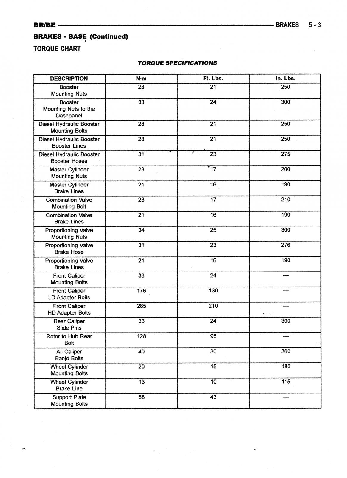
When mounting the brake brackets, calipers and hardware the proper mounting bolt torque can be critical. It is best if a torque wrench is used for this.
-
The manufacture's extended warranty is all ways better than the independent warranty companies and this extended warranty policy looks like it as good as it gets.
-
What gets me about those extended warranties is you pay for a 5 or 6 year extended warranty but the first 1to 3 years there is the factory warranty. It's like having two warranty policies at the same time. It would make more sense if the extra warranty policy didn't start until the factory on expired. Make sure the warranty covers the electronics, leaking seals and gaskets . I worked at dealers for over 20 years. A car would come in with a rear main crankshaft seal leaking. The owner thought that the extended warranty would cove it. When we'd submit a claim to the warranty company it would be denied. The extended warranty would only cover hard parts like cam shaft, pistons, ect.
-
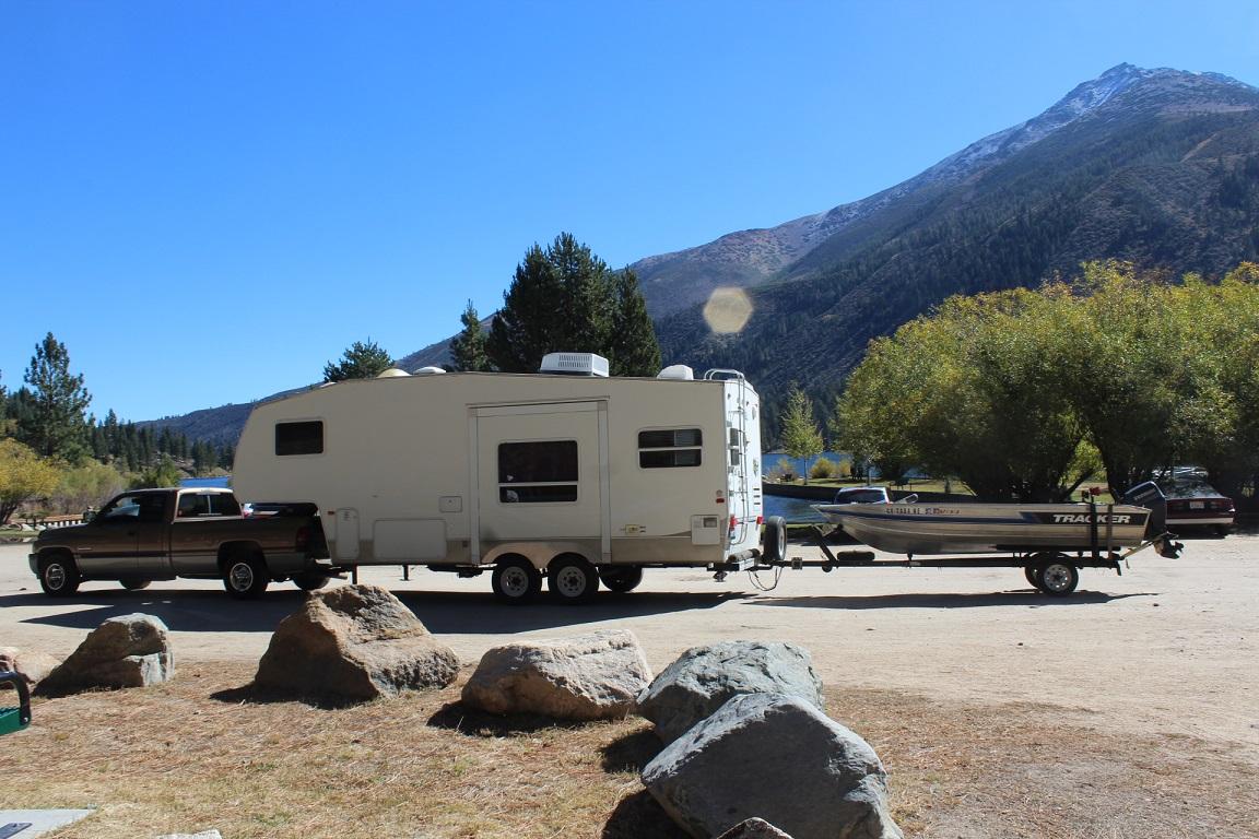
A good looking auto. I hope you have many years of trouble free driving.
-
This is my mystery switch setup: 1, a momentary switch in the shifter handle, the torque convertor lock will disengaged when brake peddle is applied 2, a lock up switch on the floor(toggle switch) with no disengagement of torque convertor when brake peddle is applied 3, an annunciator light in the A post next to the trans temp gauge that illuminates when system is on.
-
In October the AEM air filter was replaced with a Napa Gold 6637 from Amazon for $39.48
-
It would be an easy direct replacement. The Flosser 9104 is the blub to use in place of the 9004. Are you going with the 111067 or the 111068?
-
The part is described as "door, garage door opener, part #OSN98TL2AA. That's for a remote garage door opener. It's made so a remote can be placed into it, then with the cover closed the center of the cover can be pushed and the remote activated.
-
That is definitely a bad filter. Looks like an inner seal slipped over when the bottom was crimped on to the canister. Amazon is good about making thing right. I bought an ignition part that was supplied by some one else but purchased through Amazon. I ordered it on November 3, with free shipping and coming from Turkey, was to be delivered by December 16, December 22, asked for refund. I received credit to my account on December 29. The part show up on February 3 and I sent it back. Never a problem from Amazon while the people in Turkey told me to "keep checking my mail". If Amazon filled the order there should be no problem at all.
-
I've posted an article in the 24 valve 2ed generation fuel section titled "Installing Protective Lift Pump Relay". This should help explain why a relay is needed and how to install it.
-
INSTALLING PROTECTIVE LIFT PUMP RELAY The life pump is powered through the ECM via pin #15 and #35. Every time the lift pump is energized the power drawn through the ECM causes heat. After a few thousands cycles of start/stops this heating up and cooling down cause’s degradation in the solder joints and failure. Another possible cause of ECM failure is higher than normal amperage load by either a larger capacity lift pump or a failing pump. As a lift pump starts to go bad (wear internally) the AMP load is increased to overcome the resistance. This added power draw can cause the ECM circuit board to overheat and solder joints to open. The lift pump power routed through a relay protects the ECM from power spikes and excessive amperage loads. The power load on the ECM is now less than 200mA. The lift pump circuit is also protected by a dedicated fuse. MATERIALS NEEDED WIRE: 4 colors if possible, size determined by load and distance, see chart. Fuse holder with fuse: AMP rating determined by load. Relay: Bosch type/mini ISO, terminal 87 normally open (NO) with suppressor, AMP rating determined by load. 6 (or more) solderless insulated female spade connector, 6.35 mm (.25”) sized for wire gauge. 2 (or more) solderless insulated male spade connector, 6.35 mm (.25”) sized for wire gauge. 1 (or more) solderless insulated barrel connector, gauge size for fuse holder. 2 ring terminals, one sized for ground wire and the other sized for fuse holder connection. Dielectric grease, for terminal connections. Self-adhering Velcro, for attaching relay to PDC. ¼” protective wire cover or wrap cut to length. TOOLS Wire cutter Wire stripper Crimping tool for solderless connectors, a small pair of Vice-Grips will work. A 13mm and 10mm socket or wrench. Volt, ohm, amp (VOA) meter with 20amp scale. Optional, Soldering gun/iron with rosin core solder LIFT PUMP DRAW TEST Locate the ground wire for the lift pump and place the VOA meter leads in series anywhere between a grounding point and the negative terminal/wire of the lift pump. With the negative VOA lead connected to ground and the positive VOA lead on the negative side of the lift pump turn the meter select to the 20 amp DC scale, turn the ignition key to the on position and the lift pump will run for 5 seconds. Read the amp draw and make note of it. The fuse, relay and wire size will be based on it. In this example we will use a hypothetical draw of 8.6 amps. CHOOSING FUSE SIZE Finding the correct fuse size is simply multiplying the load in amps times 135% (1.35). In this example 8.6 amps multiplied by 1.35 equals 11.61 amps. The next sized fuse larger than 11.61 amps is 15 so for this example a 15 amp fuse will be used. WIRE SIZE Wire size is based on fuse size and length of wire. The wire has to be able to carry a larger load and not burn up before the fuse does. If the wire gauge is too small for a given distance then the resistance in the wire will cause a drop in voltage. This reduced voltage reaching the lift pump will cause it to run slower and produce less pressure. The voltage not reaching the lift pump is given off as heat. Using the wire gauge chart an 18 AWG is the minimum size used for this example. WHAT RELAY TO USE When an electric motor starts there can be a sharp volt/amp load placed momentarily on the relay contacts so the relay should be rated 2-3 time the motors normal amperage. The motor in this example runs at 8.61 amps times’ 3 equals 25.8 amps so the next size relay that can be used is one rated at 30 amps. The relay of choice is the mini ISO otherwise known as the Bosch type in either 4 or 5 terminal, normally open (NO). Relay terminal 30 is switched power or common in, 87 is switched power out and normally open circuit (NO) when no power is applied to the relay coil. Terminal 86 is the positive or triggering terminal and 85 is the grounding terminal for the relay coil, check relay wire diagram for specific applications. Terminal 87a is normally closed (NC) when no power is applied to the relay coil. If you find a relay marked 20/30 this means terminal 87a is rated for 20 amps and terminal is rated for 30 amps. Using a relay with a built in voltage suppressor is a must. The relay will have a resistor or diode in parallel with the relay coil. This suppressor reduces the back flowing voltage spikes to the ECM when the power to the relay is shut off and the magnetic field around the coil collapses. Most relays denote the use of a suppressor with a symbol of a resistor or diode in the wiring diagram printed or etched into the relay cover. Pay extra attention to the +,- of pins #85 and 86 when installing a relay with a suppressing diode, if not installed properly the relay can be damaged. Napa relay part #ECH AR272 is ratted for 30 amps and has a resistor suppressor. INSTALLATION INSTRUCTIONS OPTION A First disconnect the batteries. Now determine where to place the relay. The relay can be placed on the PDC with Velcro, my Edge EZ has been mounted to the PDC this way for over 12 years. This will keep the electric components in one area, a shorter wire run for relay terminal 30 and no holes in the metal where rust can start. Do not put a screw through the PDC housing; there is the risk of wire or component damage. The source of the constant 12volt power can be either the positive terminal of the left battery or for a neater installation use the large cable stud in the PDC. Install one end of the fuse holder using an appropriate sized ring terminal to the 12 volt terminal and with an insulated female spade connector attach the other end to relay terminal 30. If the wire for the fuse holder is to short connect extra length with either an insulated barrel connector or solder them together and insulate with heat shrink tubing. Find the wire harness used for the lift pump, pulling back the protective wire wrap there will be a yellow wire with white tracer (yl/wt) and a factory connector. This is the factory lift pump power supply and will be used as the ‘trigger’ to open and close the relay contacts. The power source can be verified by attaching a test light or volt meter to it and turning the ignition key to the on position, there will be 12 volts for 5 seconds. The yl/wt wire can be cut 2½”-3”from the factory connector. NOTE this is another place where an amp lode test could be performed. Connect the new correct size wire with either male/female insulated spade connectors, insulated barrel connector or solder/heat shrink to the end coming from the ECM. Attach the other end of the new wire to relay terminal 86 with an insulated female spade connector. Consult relay diagram if diode protected. Connect another new wire to relay terminal 87 with an insulated female spade connector and the other end of the wire to either the factory connector where the yl/wt wire was cut or to the lift pump itself. The picture above shows new insulated spade connectors, the wire on the left is from the ECM to terminal 86 and the wire on the right is from terminal 87 to the lift pump. The relay grounding wire is attached to relay terminal 85 with an insulated female spade connector and the other end using a ring connector to the body. The bolt that holds the PDC to the inner fender is a good spot. Reconnect batteries and test. When routing wires take care that they are kept away from moving parts, ie: steering column, have enough length so as not to pull loose and are covered with protective wire cover or wrap. Use dielectric grease on connections to keep corrosion to a minimum or solder and seal with heat shrink tube. INSTALLATION ISTRUCTION OPTION B The relay and fuse can be installed in the PDC giving it the appearance of an OEM part. Some of the connectors used in the PDC are not available in the general market but can be found in an auto/truck salvage yard. I went to a ‘pick your part’ type salvage yard and found a 1999 Ram 1500 with V8. The PDC is basically the same as my 2000 diesel. You can either buy the whole PDC or remove the terminals with wires attached that will be needed. Leave as much wire as possible; the excess can be trimmed later. Disconnect connect the battery, remove the PDC cover and locate where a spare fuse and relay can be added. Remove the two sheet metal screws (10mm socket) and lift the PDC up. The PDC housing can now be opened by gently lifting the plastic clips on the sides and prying it apart. Now the bottom of the top half is exposed. Drill a hole large enough for three wires to pass through in the lower half of the case. This is where the wires for relay terminals 85, 86 and 87 will exit the PDC. The additional wire length is added by soldering and heat shrink tubing or insulated barrel connector to the used OEM connectors. These connections will be protected in the lower half of the PDC. Pass the wires through the hole and place the salvaged connectors into their appropriate relay slots. The other end of the wires can now be trimmed to length and connected as described in the installation instructions option a above. Place the 2 halves of the PDC together and remount the PDC to the inner fender while grounding the relay terminal 85 wire with one of the screws, reconnect battery and test. My truck lift fuel pump amp draw is 6.5 amps so at 135% protection needed is 8.77 amps, next standard size fuse is 10 amps. Relay size is 3 x 6.5 amps = 19.5 amps so a 20amp rated relay is needed. I used a micro relay which is half the size of a mini relay because it can handle 20 amps and there were 4 empty positions I could put it in verses 1 position for a mini relay in the PDC. I put the relay in a spot marked for an O₂ heater. My truck has a Fuel Boss mechanical fuel pump and I have this electric pump as a backup so I run the engine with the 10amp fuse in the glove box. With a fuel pump relay the fuel system can be primed without the ignition key being turned to the on position by jumping relay terminal 30 to 87. As long as the two terminals are connected the fuel pump will run. Written by: J. Daniel Martin, Martin’s Mobile Maintenance AKA: IBMobile 3/2/2017
- 3 reviews
-
-

-

- 12
-
-
INSTALLING PROTECTIVE LIFT PUMP RELAY The life pump is powered through the ECM via pin #15 and #35. Every time the lift pump is energized the power drawn through the ECM causes heat. After a few thousands cycles of start/stops this heating up and cooling down cause’s degradation in the solder joints and failure. Another possible cause of ECM failure is higher than normal amperage load by either a larger capacity lift pump or a failing pump. As a lift pump starts to go bad (wear internally) the AMP load is increased to overcome the resistance. This added power draw can cause the ECM circuit board to overheat and solder joints to open. The lift pump power routed through a relay protects the ECM from power spikes and excessive amperage loads. The power load on the ECM is now less than 200mA. The lift pump circuit is also protected by a dedicated fuse. MATERIALS NEEDED WIRE: 4 colors if possible, size determined by load and distance, see chart. Fuse holder with fuse: AMP rating determined by load. Relay: Bosch type/mini ISO, terminal 87 normally open (NO) with suppressor, AMP rating determined by load. 6 (or more) solderless insulated female spade connector, 6.35 mm (.25”) sized for wire gauge. 2 (or more) solderless insulated male spade connector, 6.35 mm (.25”) sized for wire gauge. 1 (or more) solderless insulated barrel connector, gauge size for fuse holder. 2 ring terminals, one sized for ground wire and the other sized for fuse holder connection. Dielectric grease, for terminal connections. Self-adhering Velcro, for attaching relay to PDC. ¼” protective wire cover or wrap cut to length. TOOLS Wire cutter Wire stripper Crimping tool for solderless connectors, a small pair of Vice-Grips will work. A 13mm and 10mm socket or wrench. Volt, ohm, amp (VOA) meter with 20amp scale. Optional, Soldering gun/iron with rosin core solder LIFT PUMP DRAW TEST Locate the ground wire for the lift pump and place the VOA meter leads in series anywhere between a grounding point and the negative terminal/wire of the lift pump. With the negative VOA lead connected to ground and the positive VOA lead on the negative side of the lift pump turn the meter select to the 20 amp DC scale, turn the ignition key to the on position and the lift pump will run for 5 seconds. Read the amp draw and make note of it. The fuse, relay and wire size will be based on it. In this example we will use a hypothetical draw of 8.6 amps. CHOOSING FUSE SIZE Finding the correct fuse size is simply multiplying the load in amps times 135% (1.35). In this example 8.6 amps multiplied by 1.35 equals 11.61 amps. The next sized fuse larger than 11.61 amps is 15 so for this example a 15 amp fuse will be used. WIRE SIZE Wire size is based on fuse size and length of wire. The wire has to be able to carry a larger load and not burn up before the fuse does. If the wire gauge is too small for a given distance then the resistance in the wire will cause a drop in voltage. This reduced voltage reaching the lift pump will cause it to run slower and produce less pressure. The voltage not reaching the lift pump is given off as heat. Using the wire gauge chart an 18 AWG is the minimum size used for this example. WHAT RELAY TO USE When an electric motor starts there can be a sharp volt/amp load placed momentarily on the relay contacts so the relay should be rated 2-3 time the motors normal amperage. The motor in this example runs at 8.61 amps times’ 3 equals 25.8 amps so the next size relay that can be used is one rated at 30 amps. The relay of choice is the mini ISO otherwise known as the Bosch type in either 4 or 5 terminal, normally open (NO). Relay terminal 30 is switched power or common in, 87 is switched power out and normally open circuit (NO) when no power is applied to the relay coil. Terminal 86 is the positive or triggering terminal and 85 is the grounding terminal for the relay coil, check relay wire diagram for specific applications. Terminal 87a is normally closed (NC) when no power is applied to the relay coil. If you find a relay marked 20/30 this means terminal 87a is rated for 20 amps and terminal is rated for 30 amps. Using a relay with a built in voltage suppressor is a must. The relay will have a resistor or diode in parallel with the relay coil. This suppressor reduces the back flowing voltage spikes to the ECM when the power to the relay is shut off and the magnetic field around the coil collapses. Most relays denote the use of a suppressor with a symbol of a resistor or diode in the wiring diagram printed or etched into the relay cover. Pay extra attention to the +,- of pins #85 and 86 when installing a relay with a suppressing diode, if not installed properly the relay can be damaged. Napa relay part #ECH AR272 is ratted for 30 amps and has a resistor suppressor. INSTALLATION INSTRUCTIONS OPTION A First disconnect the batteries. Now determine where to place the relay. The relay can be placed on the PDC with Velcro, my Edge EZ has been mounted to the PDC this way for over 12 years. This will keep the electric components in one area, a shorter wire run for relay terminal 30 and no holes in the metal where rust can start. Do not put a screw through the PDC housing; there is the risk of wire or component damage. The source of the constant 12volt power can be either the positive terminal of the left battery or for a neater installation use the large cable stud in the PDC. Install one end of the fuse holder using an appropriate sized ring terminal to the 12 volt terminal and with an insulated female spade connector attach the other end to relay terminal 30. If the wire for the fuse holder is to short connect extra length with either an insulated barrel connector or solder them together and insulate with heat shrink tubing. Find the wire harness used for the lift pump, pulling back the protective wire wrap there will be a yellow wire with white tracer (yl/wt) and a factory connector. This is the factory lift pump power supply and will be used as the ‘trigger’ to open and close the relay contacts. The power source can be verified by attaching a test light or volt meter to it and turning the ignition key to the on position, there will be 12 volts for 5 seconds. The yl/wt wire can be cut 2½”-3”from the factory connector. NOTE this is another place where an amp lode test could be performed. Connect the new correct size wire with either male/female insulated spade connectors, insulated barrel connector or solder/heat shrink to the end coming from the ECM. Attach the other end of the new wire to relay terminal 86 with an insulated female spade connector. Consult relay diagram if diode protected. Connect another new wire to relay terminal 87 with an insulated female spade connector and the other end of the wire to either the factory connector where the yl/wt wire was cut or to the lift pump itself. The picture above shows new insulated spade connectors, the wire on the left is from the ECM to terminal 86 and the wire on the right is from terminal 87 to the lift pump. The relay grounding wire is attached to relay terminal 85 with an insulated female spade connector and the other end using a ring connector to the body. The bolt that holds the PDC to the inner fender is a good spot. Reconnect batteries and test. When routing wires take care that they are kept away from moving parts, ie: steering column, have enough length so as not to pull loose and are covered with protective wire cover or wrap. Use dielectric grease on connections to keep corrosion to a minimum or solder and seal with heat shrink tube. INSTALLATION ISTRUCTION OPTION B The relay and fuse can be installed in the PDC giving it the appearance of an OEM part. Some of the connectors used in the PDC are not available in the general market but can be found in an auto/truck salvage yard. I went to a ‘pick your part’ type salvage yard and found a 1999 Ram 1500 with V8. The PDC is basically the same as my 2000 diesel. You can either buy the whole PDC or remove the terminals with wires attached that will be needed. Leave as much wire as possible; the excess can be trimmed later. Disconnect connect the battery, remove the PDC cover and locate where a spare fuse and relay can be added. Remove the two sheet metal screws (10mm socket) and lift the PDC up. The PDC housing can now be opened by gently lifting the plastic clips on the sides and prying it apart. Now the bottom of the top half is exposed. Drill a hole large enough for three wires to pass through in the lower half of the case. This is where the wires for relay terminals 85, 86 and 87 will exit the PDC. The additional wire length is added by soldering and heat shrink tubing or insulated barrel connector to the used OEM connectors. These connections will be protected in the lower half of the PDC. Pass the wires through the hole and place the salvaged connectors into their appropriate relay slots. The other end of the wires can now be trimmed to length and connected as described in the installation instructions option a above. Place the 2 halves of the PDC together and remount the PDC to the inner fender while grounding the relay terminal 85 wire with one of the screws, reconnect battery and test. My truck lift fuel pump amp draw is 6.5 amps so at 135% protection needed is 8.77 amps, next standard size fuse is 10 amps. Relay size is 3 x 6.5 amps = 19.5 amps so a 20amp rated relay is needed. I used a micro relay which is half the size of a mini relay because it can handle 20 amps and there were 4 empty positions I could put it in verses 1 position for a mini relay in the PDC. I put the relay in a spot marked for an O₂ heater. My truck has a Fuel Boss mechanical fuel pump and I have this electric pump as a backup so I run the engine with the 10amp fuse in the glove box. With a fuel pump relay the fuel system can be primed without the ignition key being turned to the on position by jumping relay terminal 30 to 87. As long as the two terminals are connected the fuel pump will run. Written by: J. Daniel Martin, Martin’s Mobile Maintenance AKA: IBMobile 3/2/2017 View full Cummins article
-
Try Schenider Racing Cams 1235 Cushman Ave San Diego, CA 92110 619-297-0227
-
I'll check tomorrow with the machine shop I use. He does a lot of custom work on antique, race and industrial applications. If he can't do it he'll have a good led.
-
I'd go to Napa with the old stud. There they will be able to measure it (pitch, diameter and length) and either have one close in size, same pitch and diameter but slightly longer would work, or order it. If they don't have any available you will at least know the size. If you just want to order them straight away try this place .http://www.enterpriseengine.com/product/injection-pump-mounting-stud-p-7100-vp-44/ I hope this isn't contagious!
-
I'm trying to keep a Mexican worker in Mexico. So are you saying you don't know any good auto upholstery shops in Tijuana?
-
The leather on the front seat bottoms is starting to go bad and needs to be redone. Over the years I've heard about and seen some of the work out of upholstery shops in Tijuana for a third to half what it would cost here in the States . Tijuana is about 55 minutes south of me and my son goes down there from time to time so getting the seat bottoms there is no problem. Does anyone have any recommendations or experience with a shop there?
-
Would something like this work? Put nut on all thread bolt, place bolt with nut through large fender washer, place short peace of pipe over injector then put bolt with nut and washer into the injector. Now tighten the nut against the fender washer while counter holding the bolt head. This should 'suck' the injector out. You may have to take the valve rocker arms off but at this stage of the game what else can you do.
-
Are you talking about the Soldier Creek & Red Cloud Camp grounds? When going to an unfamiliar camp ground I pull up the site map along with Google Earth. On Google Earth I check out the sites an see what trees are near by and with the map orientated north you can see the shadows that are cast and what time of day the picture was taken. With this info I go to the site map, find the site, pull up the particulars and see if it's available. Using Google Earth you can see that a lot of the Soldier Creek camp sites have shade but not all. June is the time of the summer solstice so The sun will be straight up at noon with no large amounts of shade. There are several sites with a good amount of shade so pull up the maps and take your best shot. I also read the reviews seeing what they have to say knowing if it has one or two poor comments and the rest are fair or better then the poor ones were written by someone with their shorts in a bunch that day and are disregarded.
-
That's three hundredths of a volt. This much voltage goes right along with the amp draw of 17mA. Nothing I'd worry about. if you want to find out what is using .03V start by removing, in the junction block, one fuse at a time: #1, #4, #12, #13, #14, and circuit breaker #2.
-
I see that you're in San Diego. When registration is up for renewal will you need a SMOG inspection. If one is needed be careful of the upgrades. Most performances boxes are not CARB compliant and any smoke from tailpipe other than at start up is a failure.
