


Mopar1973Man
Owner
-
Joined
-
Last visited
Everything posted by Mopar1973Man
-
Yup... If it mounted right at the VP44 it will beat the seals right out of the sensor. I know this because it took me a few pressure switch and a few sensor before I realized what went wrong. Since now I'm relocated at the fender I've never had another problem with fuel pressure sensors or switches. If remote located anywhere make sure to have at least 5 feet of 1/8 air brake tubing. Never replace it again...
-
Not to hijack... i can match you. I fed my turbo a hose clamp. Yeah I know expensive mistakes. DAP would be a good place to call and ask about rebuilders. You might look up in your area for injection pump rebuilders. I've got one that I like is Idaho Diesel Tech in Lewiston, ID.
-
Gotta ask do you have over sized tires on the truck bigger than 265/75 R16? Larger tires do put a huge amount of strain on the steering box. Makes it worse if you have a quick ratio steering box and over sized tires. Like Ryan at Blue Top told me if your running smaller that stock tires (265 or smaller) you can run a quick ratio box. But if your going to run over sized tires (265's and larger) you need the standard ratio box to lighten the load of the steering gears and hydraulic pump.
-
You can get a pump from DAP as mention above. I personally like the injection shop rebuilders personally. I've got one in Lewiston Idaho which it is a 2 man team but like they said the old mechanical pump like p-pump are obsolete and getting more and more rare to even find them or anyone that want to rebuild them. They are now cutting hours back to only Tuesday, Wednesday and Thursday because there is not enough business to keep them open any longer. Being everything is electronic now on CR engines or VP44 engines.
-
Typically power steering fluid is a forgotten fluid no one changes. As for the clutch part. If the clutch is playing a role in noises it could be a throw bearing or pilot bearing. Typically they make noise if you press the clutch down. Like I've got a 2006 in my shop with blown throw out bearing and pressure plate fingers are worn. Every time you touched the clutch pedal it would scrap and grind noise. Let go typically the throwout bearing is just touching the finger but not seriously loaded. Pilot bearing will make noise typically when you foot is on the pedal being the input shaft is not moving or moving a different speed than the engine now that bearing will make noise. Typically pilot bearing will make it hard to shift gear either up or down. The only other subsystem is the vacuum pump but that is lube by engine oil. Never heard of a vacuum pump making a whining noise. It forward of the power steering pump. Like myself I've got 421k miles on my OEM power steering pump and never replaced it yet still working as designed!
-
What is the condition of the power steering fluid? (Amber or black) When was the last time you flush the power steering system? (Every 30k) Are you using Power fluid and not ATF? (DO NOT use ATF) Is the power steering fluid foamy when its whining? (Possibly low on fluid) As for my comment on flushing this means removing the steering box return line from the pump and route it to a waste bucket. Plug the nipple on the reservoir to allow it to hold fluid. Now with the front axle off the floor and Engine OFF key to unlock the steering wheel. Now go from lock to lock slowly. This will pump out the system. When empty fill another 3 times and pump through till the fluid is clean. Then rehook up the return line and fill. When you start it will foam up. Shut down and wait for the foam to settle about 15 to 30 minutes tops. Then top off and you should be good. Do NOT use a turkey baster to suck out the reservoir. You only getting about 1 pint out. The entire system can hold nearly 2 quarts. Steering box allow holds about a quart to itself.
-
Not enough flow rate. There is no electric fan that can keep up for our trucks. Especial for towing. There has been a few try it but most end up going back to the mechanical fan. Fan is normal just free spinning on the truck. Fully warm truck. There is no engine load to a good clutch fan till the engine reaches closer to 210*F now it will lock up. Heck I ran even for a full 2 winter without a fan to even see if there is a change of MPG from loading ... NOPE!
-
2,3,4...
-
No worse the all day affair doing a window motor in my truck door.
-
Some photos didn't show...
-
I usually right around 6 to 8 hours to tear down and reinstall the HVAC case. Typically can be done in a day. Just take the time to look at everything.
-
Yup I'd have to agree...
-
It will work just fine I've done at least a dozen heater cores now and still it takes me most of the day to do a full heater core and evaporator service. I do everything wash the two half of the HVAC case. Inspect the evaporator for oily spots if so replace. Then if it dry I will typically power wash and reused if in good condition. Then check the blend door shaft since it out you can easily change that plastic shaft if need. Change out the blower resistor if the ceramic is cracked. If resistor is poor condition replace the blower motor too being the bearings are failing which causes high load on the resistor and it over heats. Doing any cheat will skip all this and typically result in pulling it later on because of other issues. Trust me after as many as I've done now it BEST to PULL the HVAC case and do a full service and cleaning.
-
Too low the overflow valve closed at 14 PSI. You lost your cooling and lubing of the pump causing wear. You need to stay above 14 PSI for longevity. You pump doesn't have enough volume an/or your supply plumbing is too restrictive causing the pressure drop. You should have 1/2 inch lines from the fuel tank to the lift pump to the factory filter then one more between the filter and the injection pump. I'm set at 17 PSI with a Quadzilla (+180 HP), DAP 150 HP injectors (7 x 0.010) I only drop 2 maybe 3 PSI. Settle right at 15 PSI typically all the way to 100 MPH. True rebuilder should have a Bosch 815 test stand to do a proper rebuild of the pump. Yes a personal can change the parts in the pump no problem. The next step is to put the VP44 on a Bosch 815 test stand for 3 hours to tested fully and have the PSG reflashed with the calibrations. This is a requirement. Also Ive been total true Bosch rebuilder will not reuse a PSG unit on the pump it must be replace according to Bosch policies. Here is my list of certified shops. As for fuel system you need a better fuel system and keep your fuel pressure above 14 PSI at all times to keep return fuel flowing. I'm running an AirDog 150 with a 4G AirDog 165 pump. This setup is 14 years old and still going. I lost my first pump at 250k miles, 3G pump failed instantly in 3k miles, now 4G pump is solid and works awesome no issue to report. Never gelled in 18 years still going...
-
Bad ground wire was my issue with the Quad... Lenny is a cool gent he's always there in a pinch! A bit of tweak and tune... Now I'm back to taking chunks out of my rear tires. I was showing off a bit for Eileen's Son and it pull firm in 2nd against the TQ Manangement, hopped into 3rd gear boost hit 49 PSI. The tires came loose and start smoking. Grabbed 4th and got just a small bark and a bit of spin and hooked up and heading toward 5th... She is dam quick... As for the turbo difference... HX35/40 Hybrid 60mm compressor, 60mm turbine, and 12cm2 housing. As for the Stock HX35W is 54mm compressor, 60mm turbine, and 12cm2 housing... Mere 6mm difference on the compressor that's it. Flows the same amount roughly as the HE351 witthout the 9cm2 housing which is a choke point.
-
That should work out fine. I've used quite a bit of Standard Motor Products as well.
-
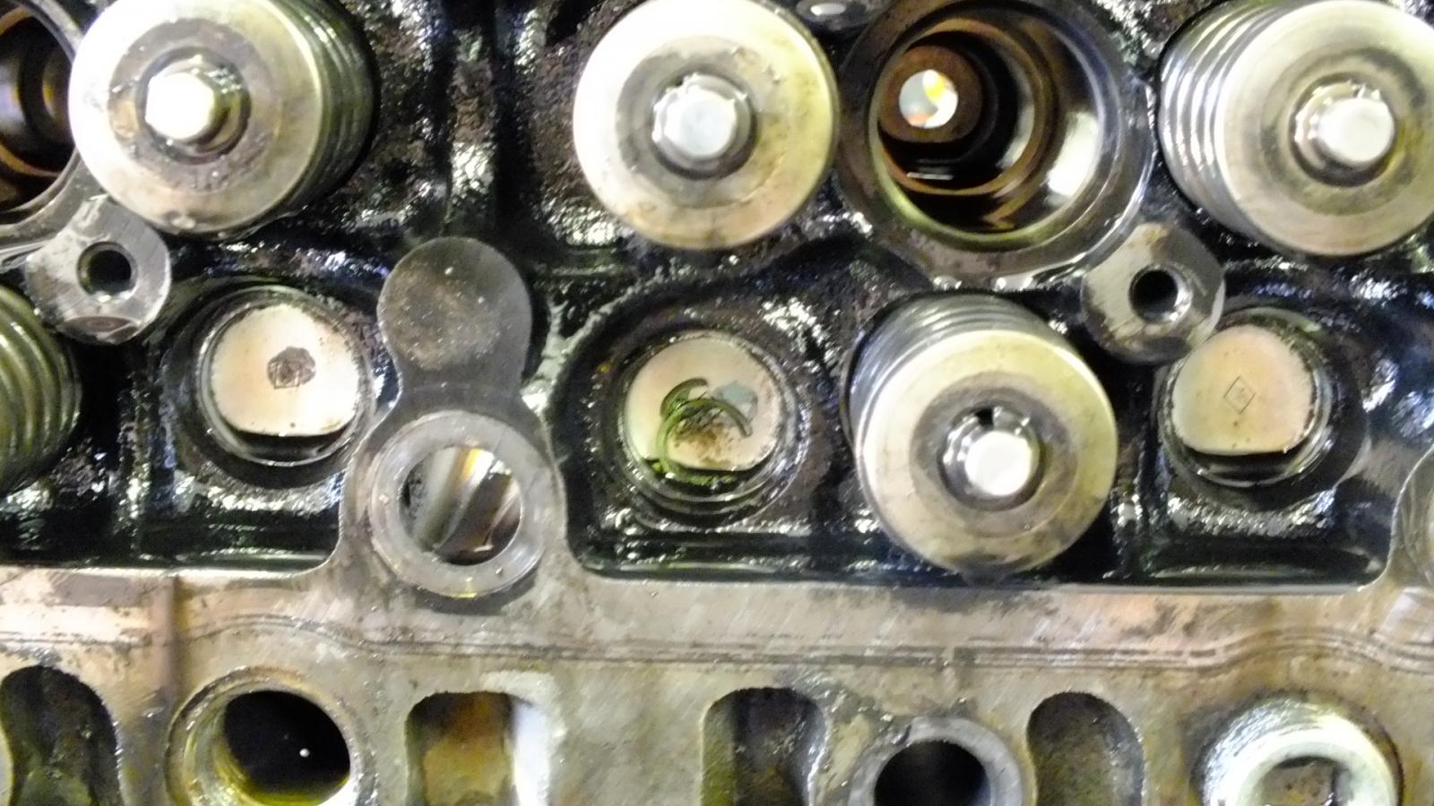
That would work... But it will only show exhaust leaks. What about intake guides and seals? Just easier to remove the valve cover and look for broken oil seals. If any are found the head will need to be removed and have new valve guides installed being the only way to ruin a oil seal is to have wore valve guides and the valve stems start to rock under the rocker arm and then the seals get brittle and tear apart. Again if you find any valve seal in the top of the head then it time to pull the head and have it sent to machine shop for repair and valve work. You cannot just install new seal and expect them to work with wore valve guides. It will ruin the new seal nearly instantly. I'll say after all the machine work, ARP 425 studs and new head gasket it was about $2,000 worth of repair and upgrade. This was back at 350k miles. Currently 421k miles and still rollling...
-
That's a shock at 90k miles. The truck must of been short trip and ran cold often. That is the only reason I can see 90k miles engine using massive amount of oil. Even with 420k miles I'm using 1 quart every 10k miles which is about the time I change oil every 10k miles. This is why the high ilde software was wrote for these truck because idle time the exhaust temps can fall very low and then start to tar up rings and valves. This typically ends with bent push rods. The other part is most people are afraid to put there foot on the throttle and heat it up. I'll stand on mine once in awhile and run the pyrometer way up past 1,200*F just to burn the carbon out of everything. Typically I cruise at lower temps like 400 to 600 EGT's (45 to 65 MPH) where cylinder temps are cool enough to build carbon. Then later down the road I might pass someone then stand on the throttle and let her get hot. Can't constantly baby these trucks.
-
Hence why I create the simple version... Then the PCM...
-
Make sure you have the right wiring then there is no modification you need to do. The only one is after you install is the W-T ground wire mod. Maybe the PCM protection fuse.
-
This is why I disconnect my grid heater in the summer to reduce wear on the relays in the summer when they are not needed.
-
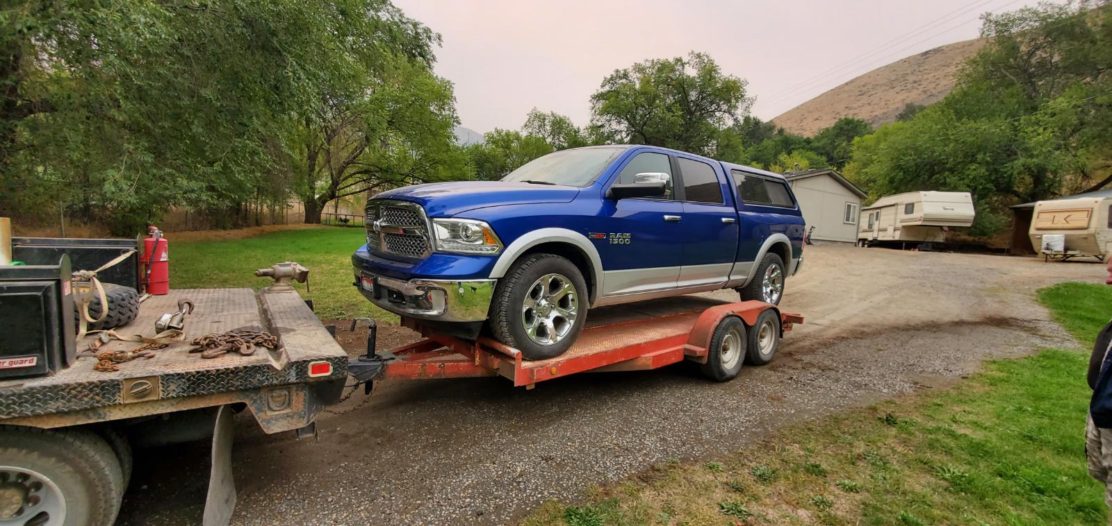
I got called to this local gents place. It's a 2017 Ram EcoDiesel. I grabbed a code reader and it had a EGR temp sensor hi code twice. Then a code for intake leak. The manifold start smoking and smells of burnt plastic when its running. Come to find out this truck has a EGR and EGR cooler recall. I told the gent that there is no sense in me fixing it for a price when the dealer can fix under the recall for free. Time passes. Now the owner of the truck gets a friend with a flat bed trailer. Calls me up because the truck will not start and there is no way to shift to neutral. Being smart I grab my phone then ask about WiFi but the gent doesn't have any but his neighbor behind him I done work in the past and got his WiFi so I found a video that explains how to shift into neutral. Basically there is a small square panel above the parking brake release you remove. When you pry that panel off you have to use a key or my pocket knife to slide the level lock over to right in the notch. Now at the same time pull the level out with the orange/red strap.You'll hear a click and now the transmission is in Neutral. We proceeded in loading up the truck so the gent can get it service on Monday. Also I really do think there injector damage too. Refuses to start or run at all. Did start and idle when I first looked at it but now no start or run. Starter spins for a mere 2-3 seconds and it just dies.
-
Like myself the ground wire came loose. The bolt I used on the hood hinge worked loose from all the vibration of washboard roads and loosened up and created all kinds of hell when the Quadzilla losing power. I part I missed on mine at least I was check +12V power but forgot the grounds.
-
Looking to buy a Quadzilla here is the links back to Quadzilla Power. 1998.5 to 2000 Dodge Ram Quadzilla Adrenaline $699.99 2001 Dodge Ram Quadzilla Adrenaline $699.99 2002 Dodge Ram Quadzilla Adrenaline $699.99
-
Here you go... My decade long study...


