


Mopar1973Man
Owner
-
Joined
-
Last visited
Everything posted by Mopar1973Man
-
I'm running 7 x 0.010 150 HP and a HX35/40 hybrid turbo. No issues. Daily driver 1,000 miles a week and getting roughly 21 MPG.
-
Should have trailer relay in the PDC. Even my 1996 Dodge has a trailer relay. But... If the trailer is not wired to that relay but the tail light wiring of the truck of course the headlight switch will get hot. This problem came from the 1st gen truck that had no trailer relay at all. But was resolved in 1994. Biggest problem is did any one modify wiring on the truck?
-
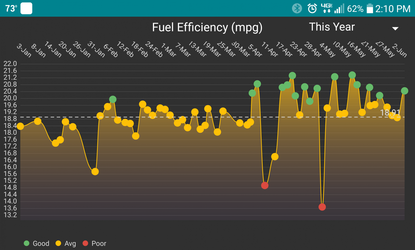
I've been logging my fuel way back 20k miles. I've still got old spread sheets and my original fuel log book. This is how I figure out what mods and such produce the best gains.
-
Need more cruise timing... 1 degree isn't enough. Bump it to 3 degrees and try again. Personally I think all the max timing needs +1 across the board.
-
I will as soon as all the drugs clear out ill be surfing on my cellphone. Promise...
-
Optimal IAT for daily driver is 100 to 140F. BHAF doesn't change IAT that much being the intercooler can only cool to the outside temp. Once the IAT falls below 80F there is a loss. I see this every day. Start at 32 to 35F in the morning by late morning when I hit Ontario I'm in the 70 to 80F temp range and creeping. Into 100 to 110F IAT and MPG rises quickly from there.
-
Not asking anything more. You are @kzimmer.
-
You need 40 warm up cycles to clear error codes. In a nutshell the coolant has to start below 140*F and then rise above 160*F. That is one warm up cycle. Then cool back down to below 140*F then rise again to above 160*F without tripping the code. It just easier to erase the codes go for a test drive and check after 10 to 15 mile drive if the code returned.
-
Suggestion... https://www.simplyauto.app/ Helps with keeping good fuel logs.
-
Upload your tune so I can look at it. I'm going to bet money the timing is set up wrong. With 6 x 0.013 injectors you going to need more timing typically but most miss the mark go either too retarded or overly advanced. The only way I found how to do timing right is keep a fuel log and run 2 to 3 tanks of fuel then make a small change in timing if you making gains in MPG keep going the same direction. Then test again. The better your timing is the lower the engine load will be. Typically economy and efficiency problems are more so timing than fuel map.
-
I'm tired and I've tried everything I can... This is why I'm great at keeping logs of everything because when some one calls me out I can produce logs and information fairly quickly. Now not to sound like an but... This is what kind upsets me about this entire thread. Lots of hear say about all kind of stuff with nothing to back up anything... At least I can come forward with screenshots and fuel logs. Even created problems on my own truck to even match the OP problems. Which is beyond the call of duty. Tell me I'm using more fuel and nothing to back up the statement, no fuel logs, or trip data. I have little belief in the statements or what been said... Where I've already produced my fuel logs and 19.58 MPG test run. https://mopar1973man.com/topic/16243-egt’s/?do=findComment&comment=211135 Then I tried reproducing massive boost leak to see if I could even get close to the OP problem, Nope... https://mopar1973man.com/topic/16243-egt’s/?do=findComment&comment=211379 Then I posted EGT's were and I produced a screenshot of my Quadzilla running down the highway at 80 MPH https://mopar1973man.com/topic/16243-egt’s/?do=findComment&comment=211461 Then people saying I'm running smaller tires. Nope, Stock sized tires. Which I'm running the exact size on the door sticker. https://mopar1973man.com/topic/16243-egt’s/?do=findComment&comment=211425 So I've done my due diligence and provided all the information and data from start to end. Peace out, I'm done...
-
Simple answer to prove this... @kzimmer make a 80 to 100 mile run down the interstate at 80 MPH and fill up before and after and do the hand math for MPG.
-
That is the software part I will agree on your right.
-
Not exactly. It is a pressure transducer but just a 1 wire. It does have a variable resistance to ground. It is NOT a switch with open (infinite ohms) and closed state (0 ohms). ECM is creating a weird value from that which follows some weird software math.
-
It is a pressure sensor. Even though its a single wire.
-
Be aware of the dash gauge its not exactly a accurate gauge. Take note this video is really old being I've not used a Edge Comp in a long time.
-
Submit a support ticket. I'm going to be delayed on looking into this being I go in for surgery tomorrow morning. At least I have a reminder to look into this.
-
The stock air filter box is rather got issues after many years that the lid can't press down enough to seal the gasket of the panel filter. As for the fibers strands I'm not worried to bad on that dirty side. It the clean side when you find things like that now I worry. So if you flip it over and look past the steel mesh that side is the one to really look at close. This is what has or will escape the filter. BHAF is the end game that will fix this problem and keep the dirt out. Yes it will flow enough air for most general daily driver usage.
-
Still considerably higher in EGT's. Being you also have 7 x 0.014 injectors vs my 7 x 0.010 injectors your for sure flowing way more fuel than I am. I see you jumped back into the high pop pressure game again. Using data from the captured screenshot. 1044 Fueling equals 25.4% Engine Load with 7 x 0.014 you flowing more flow for sure. EGT's your 184°F higher. Still better than the OP's Interesting, I'm still barely lower in drag even twisting 30" tires and 2,500 RPM vs 35" tires turning 2,000 RPM. Still running much cooler EGT's wise. Gotta say interesting to learning from data. M73M NOTE: -50°F EGT and +1 MPH for correct data. Kzimmer
-
I used to be able to tow at 55 MPH in 4th (1:1 direct). No longer with the change of tire by 1 inch. All done in top gear now. So I've gotta ask what is your MPG logs looking like?
-
Filter itself can't increase pressure it will simply go into bypass mode and continue to flow. I totally agree...
-
Dream on... Don't we wish.
-
I've only got one more surgery. As my neighbor here in Riggins just got wonderful news. I know hes been using RSO. Rick Simpson's Oil. https://www.leafly.com/news/cannabis-101/what-is-rick-simpson-oil We are suppose to meet up after my surgery. Share our stories and what cannabis secrets together.
-
@dripley Oil pressure relief valve plug not the oil pan.
-
While keeping 14 PSI... Not going to happen with a 60 GPH pump. As for the math 70% of 60 GPH is 42 GPH that has to be returned again while keeping 14 to 20 PSI not going to happen. Again its like letting the oil pressure fall to low pressure while WOT. Does the same damage to the VP44 as it would the engine. P0216 code... 4 ways to kill a VP44... Excessive AC noise Poor filtration (10 um isn't enough 3 um filters double stack is best) Low fuel pressure (14 to 20 PSI to keep the overflow valve open) Low Lubricity (<460 HFRR - US fuel is ~520 HFRR)

