


Mopar1973Man
Owner
-
Joined
-
Last visited
Everything posted by Mopar1973Man
-
All the wire maps... https://mopar1973man.com/cummins/articles.html/24-valve-2nd-generation_50/51_engine/electrical/
-
Go through the pages I've linked to and do the diagnostics and clean up the issues.
-
OMG... Geez, you guys are a tough crowd.
-
Oh damn... P0577 I don't have but... https://www.obd-codes.com/p0577
-
What error codes do you see? Did you ohm out your wiring? Did you check for 5V signal from the ECM?
-
I've thought of stuff like this but not sure what kind of possible sales we could have.
-
I'm not cheating... See its all there. No trap door.
-
P0106 - Manifold Absolute Pressure Sensor Performance Theory of Operation The Charge Air Cooler Temperature Sensor (CAC) and the Boost Pressure Sensor are combined in one sensor. This combination sensor is called the Temperature/Pressure MAP Sensor. It is located on the EGR Airflow Throttle Control Valve on the Regular Cab. For the Cab and Chassis, it is located on the Intake Manifold. The Cab and Chassis version also receives the Intake Manifold Temperature signal. The Regular Cab still has a separate Intake Manifold Temperature Sensor. The Boost Pressure Sensor is used to measure pressure in the intake manifold. The Powertrain Control Module (PCM) provides a 5-Volt supply and sensor ground for the Boost Pressure Sensor. The Boost Pressure Sensor provides a signal back to the PCM on the Boost Pressure Sensor Signal circuit. The PCM will detect a low signal voltage at operating conditions such as during an idle or a deceleration. The PCM will detect a high signal voltage during high engine load operating conditions. At key on, the readings for the Boost Pressure Sensor, Exhaust Gas Pressure Sensor, and Barometric Pressure Sensor are compared. This fault code occurs if the boost pressure reading is different from the others. During normal engine operation, the PCM estimates the Boost Pressure Sensor value using other fuel system related inputs. The PCM compares the actual Boost Pressure Sensor reading to this estimated value. If the two values are out of range for a calibrated period of time, an error is recorded. When Monitored and Set Conditions When Monitored: This diagnostic runs continuously when the following conditions are met: • With the Engine running. Set Conditions: • The Powertrain Control Module (PCM) has detected the Inlet Air Pressure Sensor value or the boost pressure reading is not within a calibrated threshold. Default Actions: • The MIL is illuminated. Possible Causes INTAKE AIR SYSTEM LEAK EGR AIRFLOW THROTTLE CONTROL VALVE PLUGGED AIR FILTER TEMPERATURE/PRESSURE MAP SENSOR Always perform the Pre-Diagnostic Troubleshooting procedure before proceeding. (Refer to 28 - DTCBased Diagnostics/MODULE, Powertrain Control (PCM) - Standard Procedure). 1. ACTIVE DTC NOTE: If DTCs P0107 or P0108 are present, repair those DTCs before proceeding. NOTE: If there are any EGR Valve or EGR Airflow Control Valve DTCs present, repair those DTCs before proceeding. NOTE: If customer states that there was an EVIC message "Service Air Filter", or if Freeze Frame Data shows "Air Filter Plugged Error equals ON", replace the Air Filter before continuing. 1. Turn the ignition on. 2. With the scan tool, record all Freeze frame data. 3. With the scan tool, erase DTCs. 4. Turn the ignition on for 75 seconds. 5. Start the engine and let idle. 6. With the scan tool, read DTCs. Did the DTC return? Yes • Go To 2 No • Perform the INTERMITTENT CONDITION diagnostic procedure. (Refer to 28 - DTC-Based Diagnostics/MODULE, Powertrain Control (PCM) - Standard Procedure). 2. CHECK FOR AN INTAKE AIR SYSTEM LEAK 1. Perform the INTAKE AIR SYSTEM PRESSURE TEST. (Refer to 29 - Non-DTC Diagnostics/Drivability - Diesel - Diagnosis and Testing) Where any leaks found? Yes • Repair the leak and perform a Mobile Desoot of the aftertreatment system. • Perform the POWERTRAIN VERIFICATION TEST - 6.7L. (Refer to 28 - DTC-Based Diagnostics/MODULE, Powertrain Control (PCM) - Standard Procedure). No • Leave the Air Inlet Tube disconnected. Go To 3 3. TURBOCHARGER 1. Inspect the impeller gear on the turbocharger for damage or broken teeth. Was there any damage found? Yes • Replace the Turbocharger assembly in accordance with the service information. • Perform the POWERTRAIN VERIFICATION TEST - 6.7L. (Refer to 28 - DTC-Based Diagnostics/MODULE, Powertrain Control (PCM) - Standard Procedure). No • Go To 4 4. CHECK THE EGR AIRFLOW THROTTLE CONTROL VALVE 1. Remove the boot from the EGR Airflow Throttle Control Valve. 2. Using a mirror, look at the butterfly valve on the inside of the EGR Airflow Throttle Control Valve. 3. Start the vehicle, let idle for 10 seconds. 4. Turn the ignition off. NOTE: If functioning properly the EGR Airflow Throttle Control Valve will cycle closed immediately after the engine is shut down. Did the EGR Airflow Throttle Control Valve cycle closed immediately after the engine was shut down? Yes • Go To 5 No • Replace the EGR Airflow Throttle Control Valve in accordance with the Service Information.(Refer to 25 - Emissions Control/Exhaust Gas Recirculation, Diesel/VALVE, Exhaust Gas Recirculation (EGR) Airflow Control/Removal) • Perform the POWERTRAIN VERIFICATION TEST - 6.7L. (Refer to 28 - DTC-Based Diagnostics/MODULE, Powertrain Control (PCM) - Standard Procedure). 5. TEMPERATURE/PRESSURE MAP SENSOR 1. Turn ignition switch on. Wait five seconds after ignition switch is turned on. 2. Using the scan tool, read DTCs Is P0106 stored? Yes • Go To 6 No • Replace the Temperature/Pressure MAP Sensor in accordance with the Service Information.(Refer to 14 - Fuel System/Fuel Injection/SENSOR, TMAP-Intake Manifold/Removal) • Perform the POWERTRAIN VERIFICATION TEST - 6.7L. (Refer to 28 - DTC-Based Diagnostics/MODULE, Powertrain Control (PCM) - Standard Procedure). 6. TEMPERATURE/PRESSURE MAP SENSOR 1. Erase the DTC with the scan tool. 2. Start the engine and let it idle for one minute. 3. With the scan tool, monitor the boost pressure reading. Does the Boost Pressure Sensor fluctuate slightly, indicating the sensor is not stuck? Yes • Repair complete. • Perform the POWERTRAIN VERIFICATION TEST - 6.7L. (Refer to 28 - DTC-Based Diagnostics/MODULE, Powertrain Control (PCM) - Standard Procedure). No • Replace the Temperature/Pressure MAP Sensor in accordance with the Service Information.(Refer to 14 - Fuel System/Fuel Injection/SENSOR, TMAP-Intake Manifold/Removal) • Perform the POWERTRAIN VERIFICATION TEST - 6.7L. (Refer to 28 - DTC-Based Diagnostics/MODULE, Powertrain Control (PCM) - Standard Procedure).
-
Adjust your throttle valve cable. Make it a bit less pull and this will lighten up more.
-
These number are just the sizes of the wheels. Compressure wheel is 62mm Turbine wheel is 67mm Exhaust housing is 12cm2 in the opening. VS. Compressure wheel is 62mm Turbine wheel is 68mm (+1 mm) Exhaust housing is 12cm2 in the opening.
-
Me. I would love to have the badge without the LED.
-
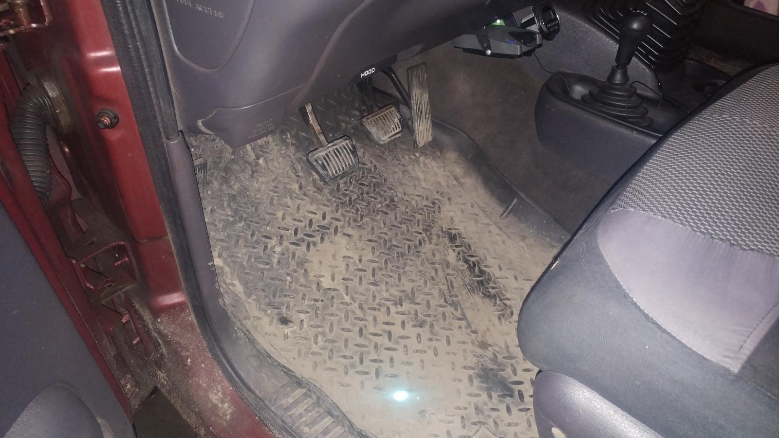
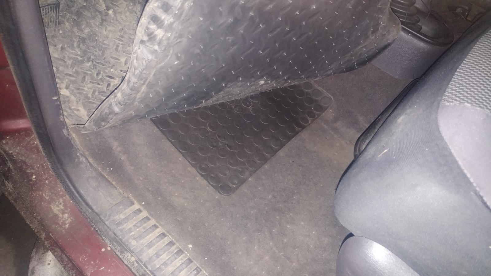
Not really. I drive like the center pedal is missing. Lot of gear usage and exhaust brake usage to get me speed below 25 MPH then my foot may touch the brake pedal. There is a lot a salt out here. Pavement is a shade of white in most places. They do get used down in Ontario from light to light. 370k miles and counting...
-
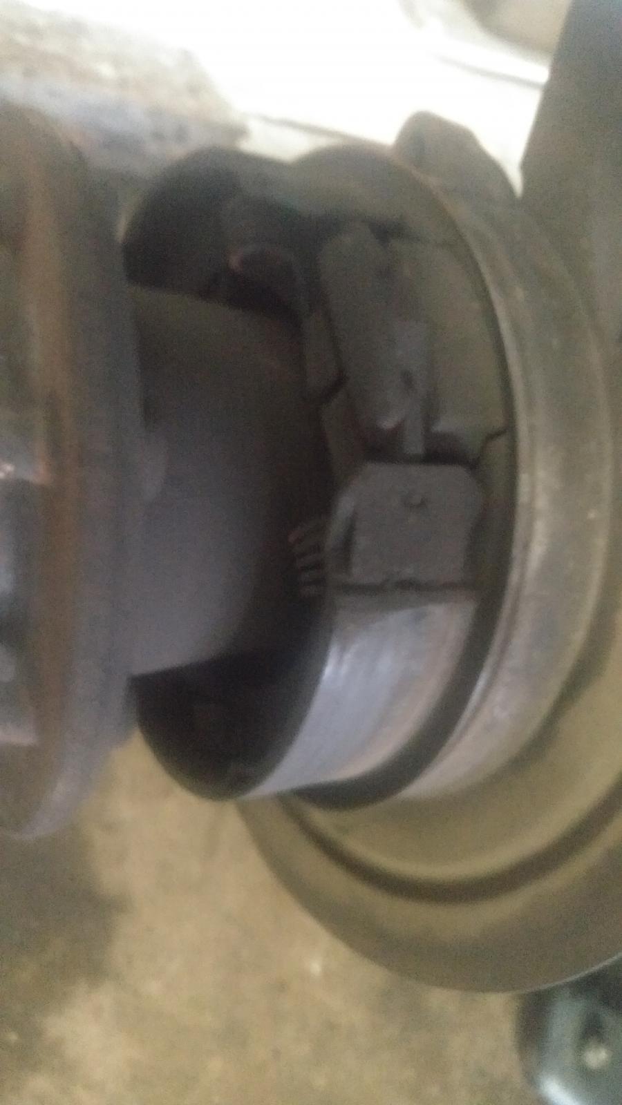
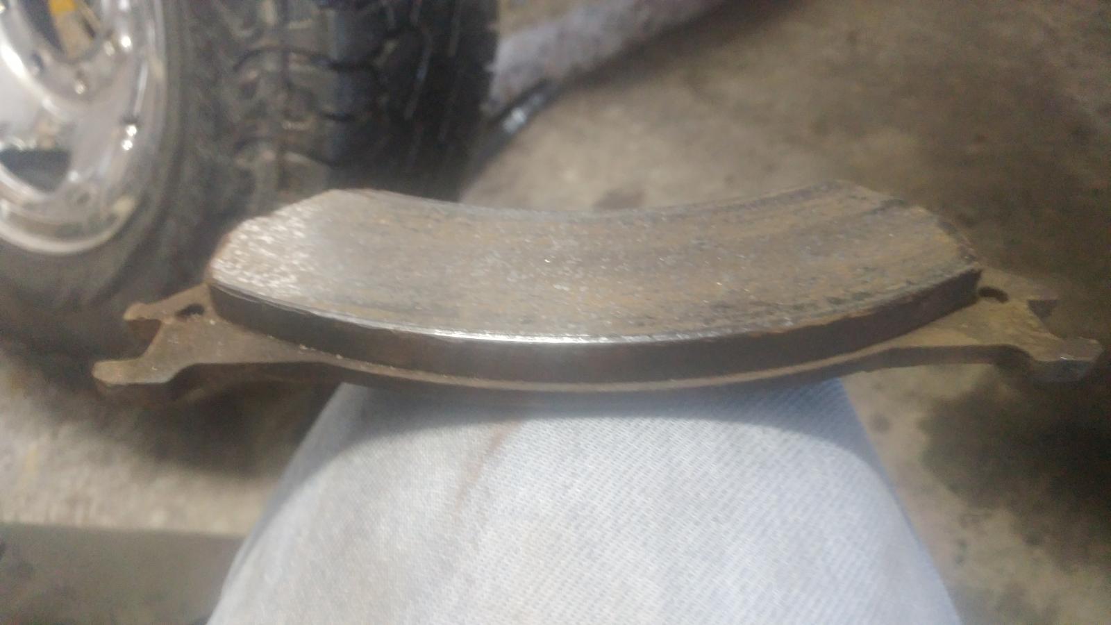
190k miles later... I'm not sure when these economy brakes will wear out?
-
Much easier... https://www.ebay.com/itm/99-02-Dodge-Ram-Overhead-Console-Map-Light-Wiring-w-Switches-MOPAR-OEM-5013609AA/333030904466?fits=Make%3ADodge&epid=1717868005&hash=item4d8a305292:g:EugAAOSwlkpcSHD~ Look like white to the center contact and the other two go to the outside contact. So no matter what the light bulb has contact to either the yellow in one position and then black in the other position. So yellow being the door pin ground or black being force ground. The pink is the +12V. While that is out change the stock bulbs for LED's less heat up there for the switch and everything.
-
Highly suggest Timbo's APPS. You current APPS is plain worn out.
-
Old school straw and able to draw to empty. I've been below 1/8 tank many times. Its all in how the tip is cut and how close to the bottom of the tank.
-
SilverStars are about the best in a halogen. Then there are the big ones 100/80w blubs... https://www.amazon.com/HELLA-100-80WTB-Wattage-100-9004/dp/B078SJ19DK/ref=sr_1_1_sspa?keywords=100%2F80w+9004&qid=1551842762&s=automotive&sr=1-1-spons&psc=1
-
I know this does directly fit but... 2nd 24V the way of disabling is the fuel pump relay being it powers the VP44 PSG unit. Without that relay for power it never will start. I agree @AH64ID the injector control wiring will keep it from starting.
-
Typically my truck run in the 450-500*F range with exhaust brake on.
-
What dust boot? Never seen one... Should be all 3 u-joints should be the same number for the front shaft.
-
Suggestion. Grab a 30 amp aux relay and wire it up to get the trigger from the fog lamp relay. Then wire the light bar through on the relay so when you toggle hi beams the light bars and headlight are in hi beam. Then when you toggle lo beam the light bars are shut down. I built this same idea with four 100w spotlights across the front of my truck. 2 bulbs were for lo beam and 2 bulbs were for hi beam. Worked awesome for years.
-
When I get home I've got a Raptor of bits and pieces. Ill pull mine out.
-
Give me a bit... I'm getting close to releasing mine. Just trying to clean up the MPG side a bit more. I pretty much got it smoke-free and runs like a cheetah on cocaine. Running 7 x 0.010 injectors and an HX35/40 hybrid (60/60/12). Thanks for letting me know about the classified area. I get after that today.
-
You're stuck. There is no LED bulb capable of being used in a factory reflector period.
-
Lucky...


